background image

EN

ES
FR

5

WARRANTY

Open Grow, LDA, guarantees the purchaser that the product is free from 
material and/or manufacturing defects. Open Grow, LDA, liability is limited 
to the repair or replacement of any defec ve parts. Do not ship directly to 
Open Grow, LDA, without first consul ng with us to verify the procedure 
that should be followed.

Contact our technical services at 

[email protected]

.

All  Open  Grow,  LDA,  products  have  a  2-year  guarantee  except  for 
consumables  (sensors  and/or  actuators  of  any  type)  and  under  normal 
use.

The loss of the “GroNode” module’s internal ba ery life as a result of its 
aging is not considered a manufacturing defect. Follow the replacement 
procedure indicated in the user manual available on your applica on or 
request more informa on from the technical services.

A guarantee claim is non-transferable and only the original purchaser can 
submit one. To enforce the guarantee the customer must always provide 
the purchase invoice.

GUARANTEE DISCLAIMER:


Applica on  of  the  guarantee  is  excluded  should  the  breakdown  of  the 
defec ve  part  or  parts  be  a  result  of  the  product’s  inadequate  and/or 
negligent use. Understood as inadequate and/or negligent use is any use 
other  than  the  one  for  which  the  product  is  meant  and/or  that  is 
recommended in the instruc ons manual, not execu ng the maintenance 
opera ons  recommended  in  the  instruc ons  manual,  carrying  out 
opera ons that are different from those men oned and that compromise 
the  quality  of  the  product,  modifica ons  that  are  not  performed  by 
authorized repairers and/or with non-original or non-approved parts.

16

Summary of Contents for GroLab TankBot

Page 1: ...www opengrow pt TANKBOT EN ES FR HW09 HW10 INSTALLATION MANUAL MANUAL DE INSTALACIÓN MANUAL L MANUEL D INSTALLATION 2019 Open Grow LDA All rights reserved IMTB2019V01 ...

Page 2: ...EN ES FR RESET USB POWER 12V 24V EC PH TEMP 1 2 3 4 I I OUTPUTS POWER OUT V1 V2 I 1 3 4 5 6 7 8 9 3 2 1 ...

Page 3: ...4 3 2 1 I I INPUTS 4 3 2 1 CONTROL 5 10 12 13 14 11 2 EN ES FR ...

Page 4: ...15 16 17 18 19 EN ES FR 3 ...

Page 5: ...ler connection outputs EC sensor outlet Temperature sensor outlet PH sensor outlet Module reset bu on 12 24VDC power supply input Sensor connec on inputs Manual switch bu ons Status signal LED Backets for wall moun ng Type B USB outlet Firmware updates RF antenna outlet ...

Page 6: ...e B cable Firmware updates 4 Pin quick connector PH probe with BNC connector 14 15 16 17 18 19 5 INSTALLATION 1 Peripherals connec on Screw the communica on antenna 14 into the module port 6 For correct communica on turn the antenna in order to posi on it ver cally according to the direc on of the module 14 6 ...

Page 7: ...the fixing holes on the upper part Once the module has been mounted connect the power cable 17 to the module s power supply input 9 and the transformer to a 110 230VAC outlet With this connec on made your module is powered and the LED indicator 13 should start to blink You also now have power availa ble on the Power output connector 1 6 ...

Page 8: ...espec ve outlets Insert the p of the plug and turn it c Never exchange the posi on of the pH and EC sensors Awrongconnec onmaydeteriorateyourdevices orthemoduleitself Calibrate the sensors using the so ware Consult the calibra on guide available by directly accessing Tutorials on your desktop Once adjusted insert the pH and EC sensors in your watertank 7 ...

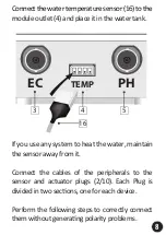
Page 9: ...thewatertemperaturesensor 16 tothe m If you use any system to heat the water maintain thesensorawayfromit Connect the cables of the peripherals to the sensor and actuator plugs 2 10 Each Plug is dividedintwosec ons oneforeachdevice Perform the following steps to correctly connect themwithoutgenera ngpolarityproblems 8 ...

Page 10: ...les To remove a wire from the plug use a pin to press the hole associated to each cable located at the surface of the plug Finally pull the cable out of the hole to remove it Connect your actuators OUTPUTS in the following order respec ng the posi on of the plug EN ES FR T t w d i t c T o p e l l t Connect your actuators OUTPUTS in the following order respec ng the posi on of the p 9 ...

Page 11: ...onnec oncan deteriorateyourdevicesorthemoduleitself Lastly connect the plugs of the sensors INPUTS and actuators OUTPUTS to their respec ve outlets EN ES FR Next carry out the same procedure on your sensors INPUTS Keepinmind thatinver ngthe polarity of the sensor you will also invert the data recorded by TankBot You can invert this polarity on the so ware without the need to re wire the s Never co...

Page 12: ...he Modules menu under the respec ve module type sec on You can check the list of modules of same type on the right side of this menu Note that one GroNode supports a maximum of 4 modules of each type 2 C Make sure GroNode is correctly installed and accessible through the GroLab So ware if not follow the instruc ons provided inside t A er installing TankBot open the GroLab So ware establish connec ...

Page 13: ...Access the Modules menu on the GroLab So ware and check if your modules are availa ble If they aren t available or they are experiencing communica on losses it is possible that you have exceeded the distance between your modules and GroNode Inside the Modules menu you can find a wireless signal icon that indicates if the selected module is connected to the GroNode NOTICE Some load bearing walls and...

Page 14: ... GroNode through all the available communica on channels un l you find your modules allowing 3 minutes between channel changes To change the communica on channel open theGroLabSo wareandconnecttotheGroNo de Inside the Main Menu Configura ons go to Se ngs GroNode General Se ngs Tab Click the bu on in the lower right corner to enable edi ng and change the communica on channel to the desired channel To...

Page 15: ...will require upda ng your devices Firmware All updates will provide crucial improve ments ensuring your system s performance Connect the type B USB cable 15 to your device s USB outlet 8 and follow the instruc ons indicated in the GroLab So ware 3 USB POWER 12V 24V 8 9 15 14 ...

Page 16: ... ated to operate with the AC power available in your loca on Do not plug the equipment power cables into an electrical outlet if the powe cable is damaged To prevent electric shock plug the equipment power cables into properly grounded electrical outlets If you use an extension power cable ensure that the total ampere ra ng of the products plugged into the extension power cable does not exceed the...

Page 17: ... user manual available on your applica on or request more informa on from the technical services A guarantee claim is non transferable and only the original purchaser can submit one To enforce the guarantee the customer must always provide the purchase invoice GUARANTEE DISCLAIMER Applica on of the guarantee is excluded should the breakdown of the defec ve part or parts be a result of the product ...

Page 18: ...ns that this product is compliant with RoHS Regula ons of the European Parliament and Council Direc ve on the Restric ons of the Use of Certain Hazardous Substances in Electrical and Electronic Equipment 2011 65 EU Open Grow LDA reserves the right to update and or modify the content of its products at any me without prior warning Check out our Terms Condi ons at www opengrow pt 6 COMPLIANCE This s...

Page 19: ...EN ES FR NOTES ...

Page 20: ...os Ninguna parte de las especificaciones se puede reproducir de ninguna forma ni por ningún medio ni se puede u lizar para obtener ningún derivado como traducción transformación o adaptación sin el permiso de Open Grow LDA ES Les spécifica ons sont suje es à changement sans préavis GroLab est une marque déposée de Open Grow LDA Les autres marques et noms de produits sont des marques commerciales ou ...

Reviews: