background image

51

Front Panel

   Rear Panel

   Remote

Contents 

  Connections 


Playback


  Setup 

Listening To the AM/FM Radio

You can receive AM and FM radio stations on this unit with the built-in tuner. 

Tuning into a Radio Station

Perform the following procedure when this unit is on.

Tuning Automatically

1. 

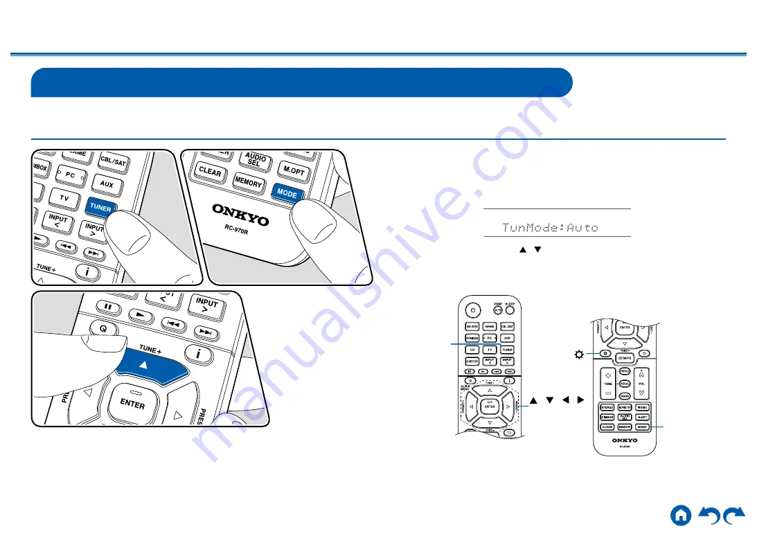
Press TUNER repeatedly to select either "AM" or "FM".

2. 

Press MODE repeatedly to display "TunMode: Auto" on the display.

3.  When you press the cursors   / 

, automatic tuning starts, and searching 

stops when a station is found. When tuned in to a radio station, the "TUNED" 

indicator on the display lights up. When tuned in to an FM radio station, the 

"FM ST" indicator lights up.

TUNER

 /   /   / 

ENTER

MODE

Summary of Contents for HT-S5910

Page 1: ...Panel Rear Panel Remote 5 1 2 CHANNEL HOME THEATER SYSTEM Instruction Manual HT S5910 En Table of contents Connections Connecting Speakers Playback Setup Troubleshooting Appendix Supplementary Inform...

Page 2: ...g Playback Devices 42 Connecting an AV Component with HDMI Jack Mounted 42 Connecting an Audio Component 44 Connecting an AV Component in a Separate Room ZONE B Connection 45 Connecting a Pre main Amp...

Page 3: ...nd Output by this Unit 75 Setup Menu 76 Menu list 76 Menu operations 78 1 Input Output Assign 79 2 Speaker 82 3 Audio Adjust 85 4 Source 87 5 Hardware 88 6 Miscellaneous 91 Quick Menu 92 Menu operatio...

Page 4: ...4 Place the supplied floor pads in position to receive the feet of the subwoofer before putting the subwoofer in place Also stick the rubber stoppers on the four corners of the base of the center spe...

Page 5: ...irm the latest firmware contents and the firmware version of your product see the following section Update Information of the firmware For the latest firmware contents and the firmware version visit o...

Page 6: ...ed with the hub function are not supported Do not connect these devices to the unit Delete any data stored on the USB storage device If HDMI CEC is set to On set it to Off Press Next select 5 Hardware...

Page 7: ...complete 8 Disconnect the USB storage device from the unit 9 Press ON STANDBY on the main unit to turn the unit into standby mode The process is completed and your firmware is updated to the latest ve...

Page 8: ...8 Contents Connections Playback Setup Front Panel Rear Panel Remote Part Names Front Panel For details see p9...

Page 9: ...the information on the display 8 DIMMER button Switches the brightness of the display with three levels It cannot be turned off completely 9 Display p10 10 SETUP button You can display advanced setti...

Page 10: ...A and separate room ZONE B 3 Lights in the following conditions Headphones are connected Connected by BLUETOOTH HDMI HDMI signals are input and the HDMI input is selected DIGITAL Digital signals are...

Page 11: ...11 Contents Connections Playback Setup Front Panel Rear Panel Remote Rear Panel For details see p12...

Page 12: ...XIAL jacks Input TV or AV component digital audio signals with a digital optical cable or digital coaxial cable 6 TUNER AM FM terminal Connect the supplied antennas 7 AUDIO IN jacks Input TV or AV com...

Page 13: ...tening mode p60 9 DIMMER button Switches the brightness of the display with three levels It cannot be turned off completely 10 CLEAR button Deletes all characters you have entered when entering text o...

Page 14: ...Panel Remote Contents Connections Playback Setup AM FM stations p51 Also when an HDMI CEC function enabled AV component is connected to this unit you can switch 3 Play buttons between CEC MODE and RC...

Page 15: ...the speaker labeled RIGHT on its back on the right side of the listening area The grille net cannot be removed 1 Wall mount hole the speaker system may be mounted to a wall by suspending speakers on...

Page 16: ...ions Playback Setup 3 Speaker jack for Front Speaker Use the included speaker cable to connect to the main unit Do not place objects on the speaker system The speaker system may drops or fall over by...

Page 17: ...ot included Please consult with a construction service personnel and prepare screw considering its type material and length so it provides sufficient support Moreover please also install a reinforceme...

Page 18: ...struction service personnel and prepare screw considering its type material and length so it provides sufficient support Moreover please also install a reinforcement panel anchor etc if necessary Our...

Page 19: ...rmal dialog or high frequency sound The indicator does not indicate that power supply of the subwoofer has turned on With the Auto Standby function the subwoofer automatically turns on when an input s...

Page 20: ...bjects being attracted or damage the oscillation panel Moreover do not place cash cards floppy disks or other magnetic media near the speaker The magnetic field may cause those items to be unusable or...

Page 21: ...ents Connections Playback Setup Connections Connecting speakers 22 Connecting the TV 39 Connecting Playback Devices 42 Connecting an AV Component in a Separate Room ZONE B Connection 45 Connecting Ant...

Page 22: ...eaker layout that suits your speakers and usage environment You can check the connection method and default settings Use height speakers Yes No When the entire supplied speaker system is connected 5 1...

Page 23: ...ers should be positioned at ear height while the surround speakers should be positioned just above ear height The center speaker should be set up facing the listening position at an angle Placing the...

Page 24: ...ear height while the surround speakers should be positioned just above ear height The center speaker should be set up facing the listening position at an angle Placing the powered subwoofer between t...

Page 25: ...rom the following 4 types according to the type of height speakers to be used and the usage environment Example installation when the entire supplied speaker system is connected p26 Example installati...

Page 26: ...g so that sound is heard after bouncing off the ceiling so that sound appears to be coming from overhead The front height speakers should be positioned at ear height while the surround speakers should...

Page 27: ...owered subwoofer between the center speaker and the front speaker gives you a natural sound even when playing music sources Front high speakers should be installed directly above the front speakers an...

Page 28: ...al sound even when playing music sources Install the top front speakers on the ceiling anterior to the seating position top middle speakers on the ceiling directly above the seating position and top r...

Page 29: ...The front speakers should be positioned at ear height while the surround speakers should be positioned just above ear height The center speaker should be set up facing the listening position at an an...

Page 30: ...tup in the Initial Setup section p94 When setting Speaker Impedance from the Setup menu press on the remote controller and set 2 Speaker Configuration Speaker Impedance p82 to 4 ohms Connect the Speak...

Page 31: ...t the Subwoofer a LINE INPUT a Subwoofer cable Connect a supplied powered subwoofer with this unit using a subwoofer cable Up to two powered subwoofers can be connected Purchase a second powered subwo...

Page 32: ...ker Installation p23 Speaker Setup settings during Initial Setup p95 Speaker Setup Speaker Channels Subwoofer Height Speaker Select how many speakers you have Next 5 1 ch Yes ENTER Speaker Channels 5...

Page 33: ...an enjoy 2 ch audio of the same source in the separate room ZONE B at the same time Purchase other separately available speaker cables if the speaker cable is not long enough Speaker Setup settings du...

Page 34: ...remove the jumper bar connecting between the woofer jacks and tweeter jacks of the Bi Amping supported speakers Refer to the instruction manual of your speakers as well Speaker Setup settings during I...

Page 35: ...available speaker cables if the speaker cable is not long enough Speaker Setup settings during Initial Setup p95 Speaker Setup Speaker Channels Subwoofer Height Speaker Select how many speakers you h...

Page 36: ...ystem is connected p26 Speaker Setup settings during Initial Setup p95 Speaker Setup Speaker Channels Subwoofer Height Speaker Select how many speakers you have Next 5 1 2 ch Yes Bundled Dolby Speaker...

Page 37: ...h Speakers Installation Example p27 Ceiling Speakers Installation Example p28 q Dolby Enabled Speakers Dolby Speakers Installation Example p29 Purchase other separately available speaker cables if the...

Page 38: ...to two powered subwoofers can be connected in either combination Speaker Channels FRONT CENTER SURROUND SURROUND BACK HEIGHT Bi AMP ZONE B ZONE SPEAKER 2 1 ch 1 1 3 1 ch 1 1 4 1 ch 1 1 5 1 ch 1 1 6 1...

Page 39: ...or play the audio of the TV on this unit Connection with the TV differs depending on whether the TV supports the ARC Audio Return Channel function or not The ARC function transmits the audio signals o...

Page 40: ...y this Unit p75 change the setting value to Enhanced Setup Settings are required to use the ARC function Select Yes for 3 ARC Setup in Initial Setup p94 If No Skip is selected settings are required in...

Page 41: ...h quality video is played use a Premium High Speed HDMI Cable or Premium High Speed HDMI Cable with Ethernet whose package has a PREMIUM Certified Cable label Furthermore in Switching the HDMI 4K Sign...

Page 42: ...gh Speed HDMI Cable with Ethernet whose package has a PREMIUM Certified Cable label Furthermore in Switching the HDMI 4K Signal Format Input and Output by this Unit p75 change the setting value to Enh...

Page 43: ...t Panel Rear Panel Remote Contents Connections Playback Setup adjusting the volume using the remote controller of a CEC compliant TV and automatically switching this unit to standby when the TV is tur...

Page 44: ...nts Connections Playback Setup Connecting an Audio Component This is a connection example of an audio component Connect a CD player using a digital coaxial cable or analog audio cable a Analog audio c...

Page 45: ...e ZONE B PRE LINE OUT jack of this unit and the LINE IN jack of the pre main amplifier or power amplifier in the separate room Setup When connecting the power amplifier set Zone B Output Level to Vari...

Page 46: ...tup Connecting Antennas Connect the antenna to this unit and set up the antenna at the best position for listening while receiving radio signals Attach the indoor FM antenna to the wall using push pin...

Page 47: ...cord after all the connections are completed Also connect the power cord of the supplied powered subwoofer The supplied powered subwoofer does not have a power switch and will come on when the power c...

Page 48: ...ts Connections Playback Setup Front Panel Rear Panel Remote Playback AV Component Playback 49 BLUETOOTH Playback 50 Listening To the AM FM Radio 51 ZONE B Playback 55 Convenience functions 57 Listenin...

Page 49: ...ut connected to the unit 2 Press the input selector whose name is the same as that of the jack to which the player is connected For example press BD DVD to play the player connected to the BD DVD jack...

Page 50: ...Onkyo HT R495 XXXXXX To connect another BLUETOOTH enabled device press and hold the BLUETOOTH button until Now Pairing is displayed and then perform step 2 This unit can store the pairing information...

Page 51: ...procedure when this unit is on Tuning Automatically 1 Press TUNER repeatedly to select either AM or FM 2 Press MODE repeatedly to display TunMode Auto on the display 3 When you press the cursors auto...

Page 52: ...ity of the reception 1 Press TUNER repeatedly to select either AM or FM 2 Press MODE repeatedly to display TunMode Manual on the display 3 While pressing the cursors select the desired radio station E...

Page 53: ...ant to register perform the following procedure 1 Press MEMORY so that the preset number on the display blinks 2 While the preset number is blinking approx 8 seconds repeatedly press the cursors to se...

Page 54: ...s TUNER 2 Press the cursors to select a preset number Deleting a Preset Radio Station 1 Press TUNER 2 Press the cursors to select the preset number to delete 3 After pressing MEMORY press CLEAR while...

Page 55: ...aying Back 1 Press ZONE A B to select an audio output destination ZONE A Outputs audio only to the main room ZONE A A on the display of the main unit lights up ZONE B Outputs audio only to the separat...

Page 56: ...vel to Variable for Speaker Setup in the Initial Setup section p94 When setting Zone B Output Level from the Setup menu press on the remote controller and set 2 Speaker Configuration Zone B Output Lev...

Page 57: ...ion 4 Perform the playback operation of the AV component such as a Blu ray Disc player To play the audio of BLUETOOTH the following step 5 operation is required 5 To play the audio of BLUETOOTH press...

Page 58: ...s or moderates the low tone range of the front speakers 2 Press or for adjustment Adjusting VOCAL Emphasizes movie lines and music vocals to listen to them more easily It is effective to movie lines i...

Page 59: ...ly when the specified time has elapsed Press SLEEP button on the remote controller to select the time from 30 min 60 min and 90 min Off The unit does not automatically enter standby mode You can also...

Page 60: ...epeatedly to switch the modes displayed on the display of the main unit Each of STEREO MOVIE TV and MUSIC buttons stores the listening mode that was selected last If content incompatible of the listen...

Page 61: ...FO button on the main unit repeatedly will switch the display of the main unit in the following order When using a BLUETOOTH connection press the INFO button on the main unit Not all the information i...

Page 62: ...Dolby Audio DD 1 1 1 2 2 2 2 2 DD Dolby Audio DD 1 1 1 1 1 1 1 1 1 DTHD Dolby Audio TrueHD 1 1 1 1 1 1 1 1 1 Atmos 2 0 2 1 Atmos 3 0 3 1 Atmos 4 0 4 1 Atmos 5 0 5 1 Atmos 6 0 6 1 Atmos 7 0 7 1 Atmos...

Page 63: ...DTS X DTS Neural X DTS Virtual X Multich Multichannel 1 1 1 1 1 3 3 3 DSD 1 1 1 2 2 2 2 2 Direct 1 1 1 1 1 1 1 1 1 Stereo 4 4 4 4 4 4 4 4 4 Mono 4 4 4 4 4 4 4 4 4 Full Mono AllCh Stereo Orchestra Stud...

Page 64: ...speaker and surround speakers are installed Atmos 6 0 6 1 When front speakers surround speakers and surround back speakers are installed Atmos 7 0 7 1 When front speakers center speaker surround spea...

Page 65: ...d a maximum of 7 1 channels with additional channels such as the surround back channel 7 1 ch is recorded at 96 kHz 24 bit and 5 1 ch is recorded at 192 kHz 24 bit To enable transfer of this audio for...

Page 66: ...pectively This mode cannot be selected when Dolby signal is input DTS Virtual X DTS Virtual X listening mode uses the proprietary audio processing technology to create spacious 3D sound including audi...

Page 67: ...the natural reverberation of a large hall Stereo In this mode sound is output from the right and left front speakers and subwoofer Studio Mix This mode is suitable for rock or pop music This mode crea...

Page 68: ...installed 4 A center speaker surround speakers or height speakers need to be installed Input Format Listening Mode PCM Direct Mono DSur DTS Neural X 1 DTS Virtual X 2 3 TV Logic 4 AllCh Stereo 5 Full...

Page 69: ...hen the input format is 2 ch 2 A center speaker or surround speakers need to be installed 3 If the input source is Blu ray Disc and the speaker layout is 5 1 ch or less DD cannot be selected Instead t...

Page 70: ...eaker Virtualizer is set to Off 5 Cannot be selected when height speakers are installed 6 Surround speakers or height speakers need to be installed 7 A center speaker surround speakers or height speak...

Page 71: ...istening Mode Multich PCM Direct Stereo Multich 1 DSur DTS Neural X DTS Virtual X 2 3 Orchestra 4 Unplugged 4 Studio Mix 4 AllCh Stereo 5 Full Mono 5 1 A center speaker or surround speakers need to be...

Page 72: ...speakers need to be installed 3 Surround speakers or height speakers need to be installed 4 A center speaker surround speakers or height speakers need to be installed Input Format Listening Mode DTS...

Page 73: ...d speakers or height speakers need to be installed 7 A center speaker surround speakers or height speakers need to be installed Input Format Listening Mode DTS HD MSTR Direct Stereo DTS HD MSTR 1 2 DT...

Page 74: ...Unplugged 3 Studio Mix 3 AllCh Stereo 4 Full Mono 4 1 Cannot be selected if Speaker Virtualizer is set to Off 2 Cannot be selected when height speakers are installed 3 Surround speakers or height spea...

Page 75: ...e main unit repeatedly press ON STANDBY to switch the setting Standard Default Value Select when the AV component connected to this unit such as a TV or player supports the standard 4K signal format 4...

Page 76: ...ening position p84 4 Level Calibration Adjust the volume level of each speaker p84 5 Dolby Enabled Speaker Change the settings of Dolby Enabled Speakers p85 6 Speaker Virtualizer The Speaker Virtualiz...

Page 77: ...for the Bluetooth function p90 3 Power Management Change the settings for the power save function p90 6 Miscellaneous 1 Tuner Change the frequency step for the tuner p91 2 Firmware Update Change the...

Page 78: ...display the Setup menu Setup 1 Input Output Assign 4 Source 6 Miscellaneous 5 Hardware 2 Speaker 3 Audio Adjust 1 TV Out OSD 4 Analog Audio Input 2 HDMI Input 3 Digital Audio Input Select the item wi...

Page 79: ...not to display information such as volume adjustment or switching of input on the TV screen On OSD is displayed on the TV Off OSD is not displayed on the TV OSD may not be displayed depending on the...

Page 80: ...t an HDMI IN jack already assigned to another input selector change its setting to first STRM BOX HDMI 4 HDMI 1 to HDMI 4 Assign a desired HDMI IN jack to the STRM BOX button If you do not assign a ja...

Page 81: ...ITAL IN jack to the TV button Supported sampling rates for PCM signals stereo mono from a digital input are 32 kHz 44 1 kHz 48 kHz 88 2 kHz 96 kHz 16 bit 20 bit and 24 bit 4 Analog Audio Input Change...

Page 82: ...ne B speaker terminals No When speakers are not connected to Zone B speaker terminals This setting is fixed to No if Bi Amp is set to Yes This setting cannot be selected when surround back speakers or...

Page 83: ...ing Item Default Value Setting Details Surround 100 Hz Select the crossover frequency from 40 Hz to 200 Hz to start outputting frequencies for each channel Full Band Full band will be output Full Band...

Page 84: ...g Item Default Value Setting Details Front Left 0 dB Select a value between 12 dB and 12 dB in 1 dB increments A test tone will be output each time you change the value Select the desired level Center...

Page 85: ...een On and Off Setting Item Default Value Setting Details Speaker Virtualizer On On Listening modes such as T D that have virtual speaker effects can be selected Off Listening modes such as T D that h...

Page 86: ...s function is set to Off the ES Matrix and ES Discrete listening modes cannot be selected Dialog Control 0 dB You can increase the volume of dialog portion of the audio up to 6 dB by 1 dB step so that...

Page 87: ...ER To name a preset radio station press TUNER on the remote controller select AM FM and select the preset number This cannot be set if the BLUETOOTH input is selected Audio Select Select the priority...

Page 88: ...function Setting Item Default Value Setting Details HDMI CEC Off Setting this to On enables the input selection link and other link functions with HDMI connected CEC compatible device On When this fun...

Page 89: ...the unit on and switch the input When using a CEC compliant TV you can reduce the power consumption in standby mode by selecting Auto Eco Setting Item Default Value Setting Details Audio TV Out Off Y...

Page 90: ...Setting Item Default Value Setting Details Pairing Information You can initialize the pairing information stored on this unit Pressing ENTER when Clear is displayed initializes the pairing information...

Page 91: ...to the POWER OUT port even if this unit is in standby mode The POWER OUT jack is cannot supply power to smart phones tablets or other devices While using this function power consumption increases in...

Page 92: ...s of the remote controller and press ENTER to confirm your selection Use the cursors to change the settings To return to the previous screen press To exit the settings press Q HDMI A V Sync If the vid...

Page 93: ...e adjustments you made will be restored to the previous statuses AccuEQ AccuEQ Enable or disable the equalizer function that corrects for sound distortion caused by the acoustic environment of the roo...

Page 94: ...anguage selection screen is displayed on TV select the language with the cursors and press ENTER Select the item with the cursors of the remote controller and press ENTER to confirm your selection To...

Page 95: ...test tone at high volume during measurement so be careful of your surroundings Also keep the room as quiet as possible during measurement If you connect a subwoofer check the power and volume of the...

Page 96: ...device The AV receiver contains a microPC for signal processing and control functions In very rare situations severe interference noise from an external source or static electricity may cause it to l...

Page 97: ...and connected devices Resetting the unit this resets the unit settings to the default If the restart of the unit does not solve the problem reset the unit and restore all the settings to the factory d...

Page 98: ...off unexpectedly If 5 Hardware Power Management Auto Standby on the Setup menu is activated the unit automatically enters the standby mode The protection circuit function may have operated due to an a...

Page 99: ...g mode not much sound may be output from speakers Select another listening mode to see if sound is output If surround back speakers are installed be sure to install surround speakers as well A maximum...

Page 100: ...e Cannot select a desired listening mode Depending on the connection status of the speaker some listening modes may not be selected Refer to Speaker Layouts and Selectable Listening Modes p62 or Input...

Page 101: ...nction refer to 5 Hardware HDMI in the Setup menu Check if Resolution Error is displayed on the main unit display when video input via HDMI IN jack is not displayed In this case the TV does not suppor...

Page 102: ...io wave in the 2 4 GHz range A metallic object near the unit can affect on the radio wave and BLUETOOTH connection may not be possible Check the following if the problem persists after you have confir...

Page 103: ...of the display p9 Others Strange noise can be heard from the unit If you have connected another device to the same outlet as this unit strange noise may occur under the influence of the device If the...

Page 104: ...cannot supply power to smart phones tablets or other devices The POWER OUT jack on the rear panel is only intended to supply power 5 V 1 A to the Streaming media player connected to HDMI IN jack of th...

Page 105: ...the following devices As of January 2019 Toshiba brand televisions Sharp brand televisions Onkyo and Integra brand RIHD compatible players Toshiba brand players and recorders Sharp brand players and r...

Page 106: ...720 576i 50 Hz 720 480p 60 Hz 720 576p 50 Hz 1920 1080i 50 60 Hz 1280 720p 24 25 30 50 60 Hz 1680 720p 24 25 30 50 60 Hz 1920 1080p 24 25 30 50 60 Hz 2560 1080p 24 25 30 50 60 Hz 4K 3840 2160p 24 25 3...

Page 107: ...e Control Characteristics 10 dB 20 Hz BASS 10 dB 20 kHz TREBLE Signal to Noise Ratio 109 dB IHF A LINE IN SP OUT Speaker Impedance 4 16 Headphone Rated Output 80 mW 80 mW 32 1 kHz 10 THD Supported imp...

Page 108: ...igital Plus DTS DTS X DTS HD Master Audio DTS HD High Resolution Audio DTS 96 24 DTS ES DTS Express DSD PCM Conversion Input 2 channel linear PCM Multi channel linear PCM HDCP version 2 2 Maximum Vide...

Page 109: ...type color coded Other Non magnetic shielding Center speaker SKC 594 Speaker Type 2 Way Bass Reflex Drivers Woofer 3 1 4 8 cm Cone 2 Tweeter 1 2 5 cm Balanced dome Frequency Response 65 Hz 50 kHz Out...

Page 110: ...150 Hz Dimensions W H D Including terminal projections 317 5 mm 463 mm 398 mm 12 1 2 18 1 4 15 11 16 Weight 9 6 kg 21 2 lbs Rated output Power IEC 120 W at 4ohms 100 Hz 1 THD Maximum Effective Output...

Page 111: ...SN 29403779_EN C Copyright 2019 Onkyo Pioneer Corporation Japan All rights reserved F1907 0...

Reviews: