


11 - 19
11 Adjustment Functions
G5-series Linear Motors/Servo Drives With Built-in EtherCAT Communications
11-5 Dam
p
in
g Co
ntr
o
l
11
11
-5-3
Oper
ating Procedure
1
Adjust the Position Loop Gain 1 (3100 hex), Speed Loop Gain 1 (3101 hex), Speed Loop
Integral Time Constant 1 (3102 hex), and Force Command Filter Time Constant 1
(3104 hex) settings.
If no problem occurs in realtime autotuning, you can continue to use the settings.
2
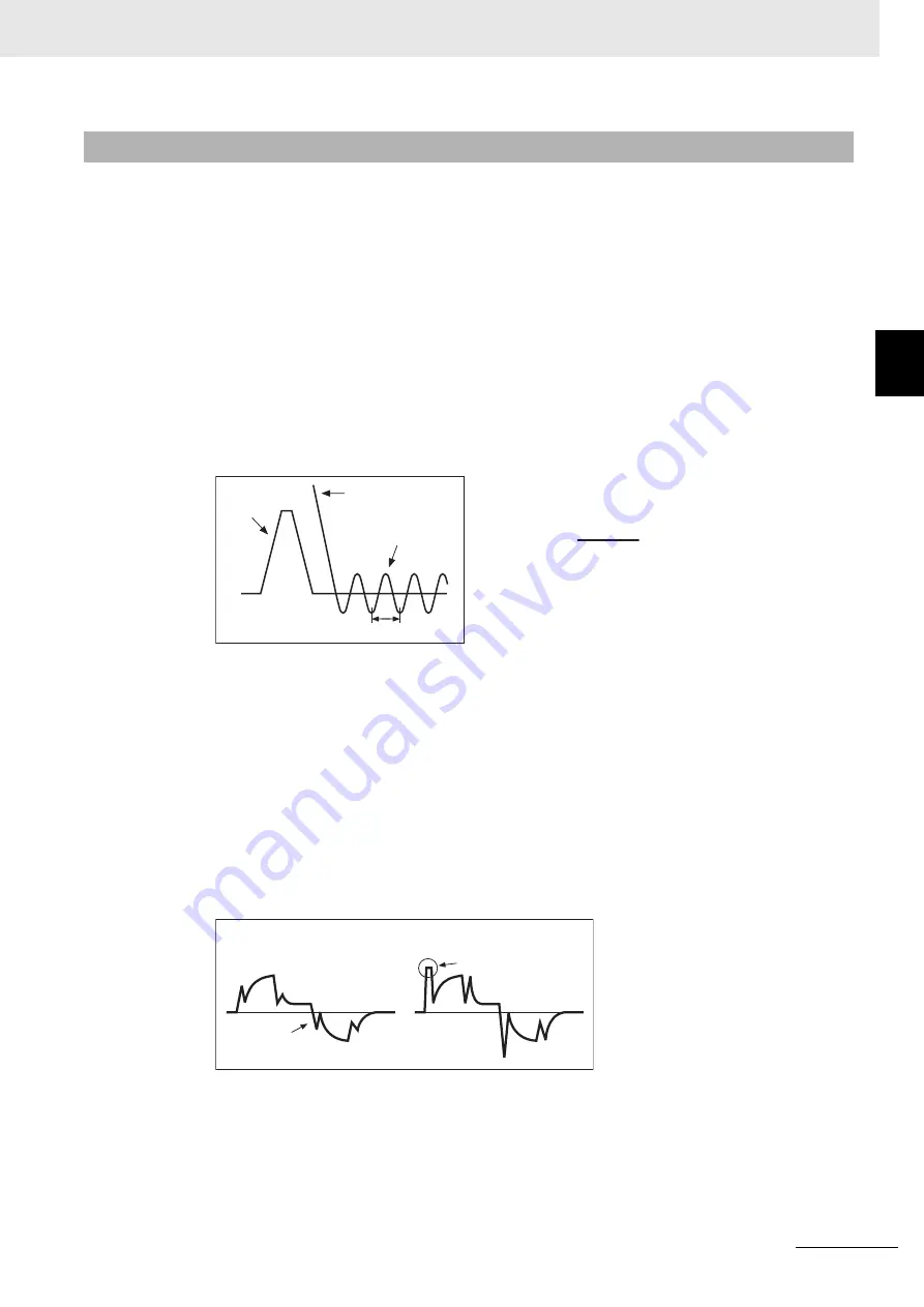
Measure the damping frequency at the tip of the mechanical unit.
Measure the damping frequency by using a measurement device such as a laser displacement
sensor, servo acceleration meter, or acceleration pick-up.
Set the measured damping frequency in one of Damping Frequency 1 to Damping Frequency 4
according to the operation.
Also set the Switching Mode using Damping Filter Selection (3213 hex).
If the measurement device cannot be used, use CX-Drive tracing function, and read the residual
damping frequency [Hz] from the Following Error Actual Value waveform as shown in the
following figure.
If vibration persists after setting the frequency, increase or decrease the resonance frequency to
find a proper one with minimum vibration.
3
Make the damping filter 1 to 4 settings.
First, set the filter to 0 and check the force waveform during operation.
The stabilization time can be reduced by setting a large value; however, force ripple will increase
at the command change point as shown in the following figure. Set a range that will not cause
force saturation under actual operation conditions. The effects of vibration suppression will be
lost if force saturation occurs.
When a Damping Frequency is set, reduce this setting if force saturation occurs or increase this
setting to increase operation speed. Normally 0 is set.
The setting range is as follows:
11-5-3 Operating Procedure
Command
speed
Following error
actual value
Calculate the
damping frequency.
Damping cycle T
•
The damping frequency in the figure is calculated
with the following formula:
Since the object unit is 0.1 Hz:
(3214 hex, 3216 hex, 3218 hex, 3220 hex)
= 10 × f
•
Application example
If the damping cycle is 100 ms or 20 ms, set 100 or
500 in the object so that the damping frequency
becomes 10 Hz or 50 Hz.
1
T [s]
f [Hz] =
Force
command
Force saturation
Damping filter setting is
too large.
Damping filter setting is
appropriate.
Damping filter setting range: Damping filter setting ≤ Damping frequency
100 ≤ (Damping fre Damping filter setting)


