9 - 11
9 Servo Parameter Objects
G5-series Linear Motors/Servo Drives With Built-in EtherCAT Communications
9-2 Gain
Setti
ngs
9
•
Set the time constant for the first-order lag filter inserted into the feed-forward.
•
Setting the filter may improve operation if speed overshooting occurs or the noise during operation is
large when the feed-forward is set high.
For details, refer to 11-10 Feed-forward Function on page 11-32.
•
Select either PI/P operation switching or Gain 1/Gain 2 switching.
•
The PI/P operation switching is performed with the Speed Loop P/PI Control command in EtherCAT
communications.
Refer to 7-9 Gain Switching Function on page 7-26 for the Gain 1/Gain 2 switching.
Explanation of Settings
•
Select the conditions for switching between Gain 1 and Gain 2 when the Gain Switching Input
Operating Mode Selection (3114 hex) is set to 1.
Explanation of Settings
(
3
: Enabled/–: Disabled)
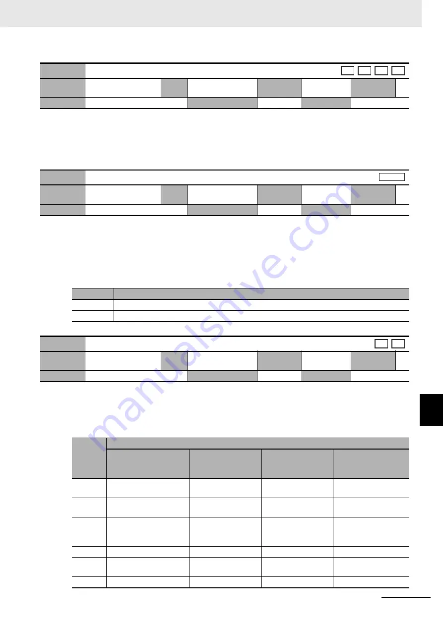
3113 hex
Force Feed-forward Command Filter
Setting
range
0 to 6,400
Unit
0.01 ms
Default
setting
0
Data
attribute
B
Size
2 bytes (INT16)
Access
RW
PDO map
Not possible
3114 hex
Gain Switching Input Operating Mode Selection
Setting
range
0 to 1
Unit
–
Default
setting
1
Data
attribute
B
Size
2 bytes (INT16)
Access
RW
PDO map
Not possible
Set value
Description
0
Gain 1 (PI/P switching enabled)
1
Gain 1/Gain 2 switching available
3115 hex
Switching Mode in Position Control
Setting
range
0 to 10
Unit
–
Default
setting
0
Data
attribute
B
Size
2 bytes (INT16)
Access
RW
PDO map
Not possible
3115 hex
set value
Description
Gain switching
conditions
Gain Switching Delay
Time in Position
Control (3116 hex)
*1
Gain Switching
Level in Position
Control (3117 hex)
*2
Gain Switching
Hysteresis in Position
Control (3118 hex)
*3
0
Always Gain 1 (3100 to
3104 hex).
–
–
–
1
Always Gain 2 (3105 to
3109 hex).
–
–
–
2
Gain switching command
input via EtherCAT
communications
*4
–
–
–
3
Force command
3
3
[%]
3
[%]
4
Always Gain 1 (3100 to
3104 hex).
–
–
–
5
Speed command
3
3
[mm/s]
3
[mm/s]
csp csv
pp
hm
A l l
csp
pp


