


3
Robot settings
3-19
2.4.2 Sensor method
(R6YXG500, R6YXG600, R6YXGH600, R6YXG700, R6YXG800, R6YXG900, R6YXG1000)
(R6YXGS500, R6YXGS600, R6YXGS700, R6YXGS800, R6YXGS900, R6YXGS1000)
■
Adjusting the X-axis machine reference
CAUTION
The origin position may change due to machine reference adjustment. If it occurs, you must set point data again.
Follow the steps below to adjust the X-axis machine reference value.
Prepare a hex wrench set.
1
Turn on the controller.
Check that no one is inside the safety enclosure, and
then turn on the controller.
2
Perform the absolute reset.
Perform the absolute reset from outside the safety
enclosure.
For details about how to perform the absolute reset,
see "2.3 Absolute reset procedures".
3
Check the machine reference value.
If the machine reference value displayed on the
pbEX/pb is not in the range between 40 and 60
(recommended range) after the absolute reset has
been completed, follow the steps below to adjust the
machine reference value.
4
Place a sign indicating the robot is
being adjusted.
Place a sign indicating the robot is being adjusted, to
keep others from operating the controller or operation
panel.
5
Turn off the controller.
6
Enter the safety enclosure.
7
Put a mark at the origin position.
Scribe a mark at the current origin position on the
X-axis joint area of the robot.
At this time, be careful to prevent the origin position
from deviating since the X-axis arm is touched.
8
Remove the cover.
Remove the cover while referring to
"13. Detaching or attaching the covers" in Chapter 2.
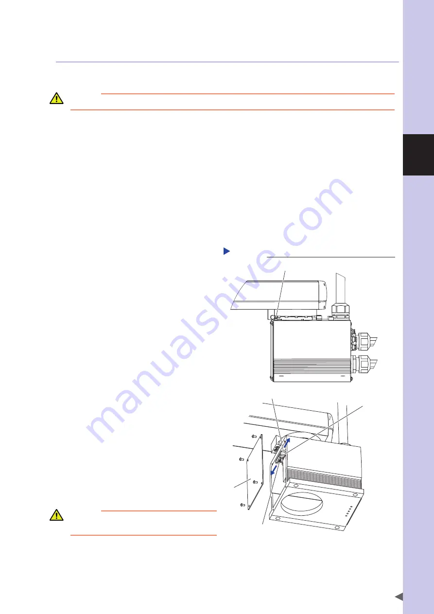
Adjusting the X-axis machine reference
(R6YXG500 to R6YXG1000)
Step 8-16
X-axis origin dog
X-axis origin sensor stay
X-axis origin sensor
Bolt
Cover
(a)
(b)
9
Scribe a mark at the X-axis origin
sensor stay position.
10
Loosen the bolts.
Using the hex wrench, loosen the bolts (2 pcs.) that
secure the X-axis origin sensor stay.
CAUTION
It is enough to loosen the bolt. Do not remove the nut
completely.
Summary of Contents for R6YXG500
Page 1: ...ZX T Series Cat No I155E EN 03A R6Y XG series INSTALLATION MANUAL SCARA Robots XG Series...
Page 2: ......
Page 10: ......
Page 36: ......
Page 38: ......
Page 40: ......
Page 46: ......
Page 48: ......
Page 56: ......
Page 174: ......
Page 176: ......
Page 220: ......
Page 221: ...Chapter 4 Periodic inspection Contents 1 Overview 4 1 2 List of inspection items 4 2...
Page 222: ......
Page 226: ......
Page 227: ...Chapter 5 Harmonic drive replacement period Contents 1 Overview 5 1 2 Replacement period 5 2...
Page 228: ......
Page 232: ......
Page 238: ......
Page 240: ......
Page 244: ......
Page 246: ......
Page 323: ...8 Specifications 8 77 1 3 Robot inner wiring diagram Robot inner wiring diagram R6YXG500...


