


2
Installa
tion
2-68
8.
Limiting the movement range with Z-axis mechanical stopper
As option parts are ordered, and then they are installed, the Z-axis movement range can be narrowed.
WARNING
bEFoRE STARTInG THE WoRK, THoRoUGHLY REAd "13. dETACHInG oR ATTACHInG THE CovERS" In THIS
CHApTER.
WARNING
ALWAYS TURn oFF THE ConTRoLLER bEFoRE CHAnGInG THE movEmEnT RAnGE WITH mECHAnICAL SToppERS.
WARNING
WHEn InSTALLInG THE pLUS dIRECTIon SToppER on THE R6YXGH600, R6YXG700, R6YXG800, R6YXG900,
R6YXG1000, R6YXGS700, R6YXGS800, R6YXGS900 oR R6YXGS1000, THE Z-AXIS ACCELERATIon mAY nEEd To
dECREASE. FoR dETAILS, SEE "8.2.2 InSTALLInG THE pLUS dIRECTIon SToppER".
CAUTION
After the mechanical stopper positions are changed, the soft limits must be set to a point inside the mechanical stopper positions.
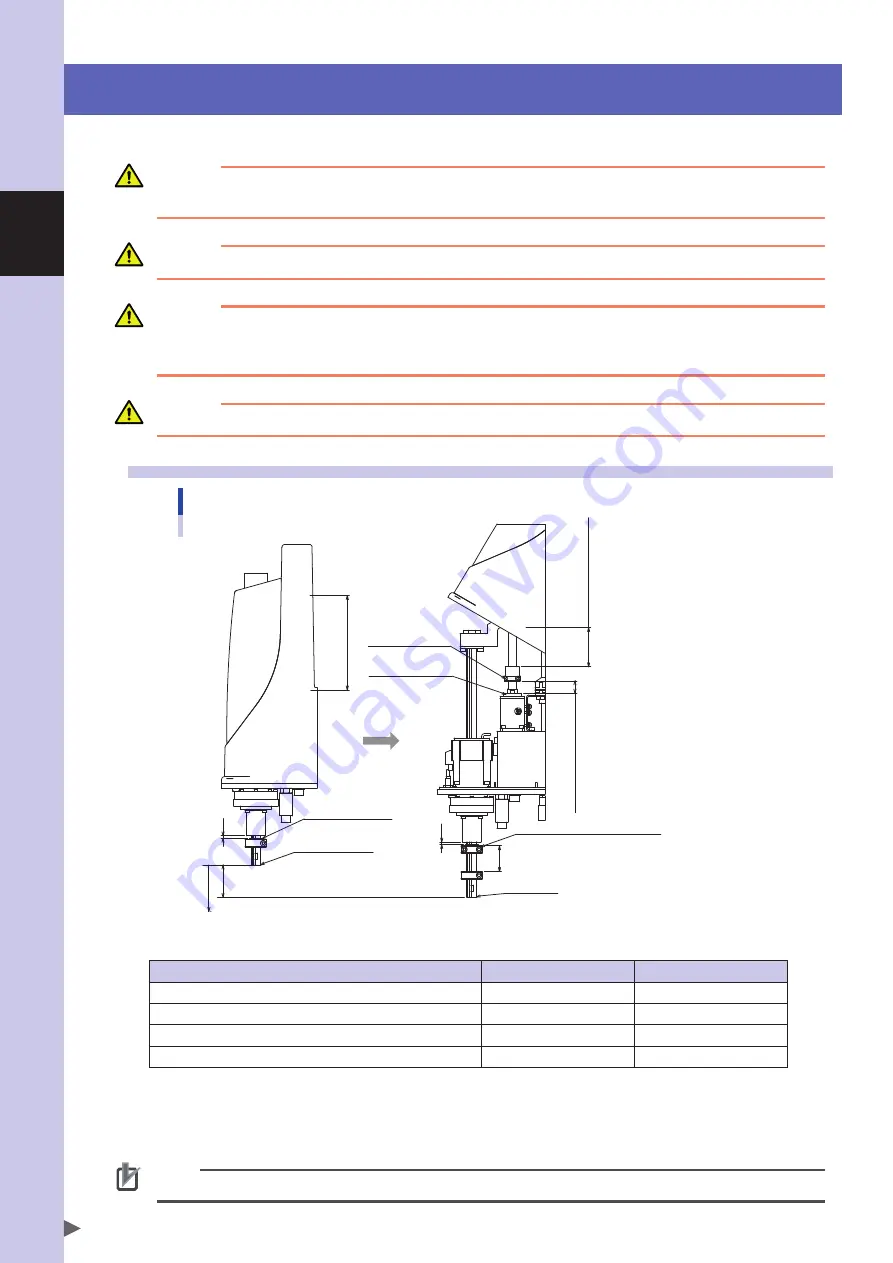
8.1
R6YXGL250, R6YXGL350, R6YXGL400, R6YXGL500, R6YXGL600, R6YXGS300, R6YXGS400
Limiting the movement range using Z-axis mechanical stopper
Working envelope 137.4-(L
1
+L
2
)
Movement range 141.4-(L
1
+L
2
)
L1 (Keep a distance of 4 mm or more.)
Added minus direction stopper
Origin position after changed (after Z-axis absolute reset)
L
2
= 12, 15, 18, ......
(At intervals of 3 mm above the Z-axis origin reference)
New origin
L
2
Additional plus
direction stopper
4
Standard plus
direction stopper
Working envelope 150 Movement range 154
Standard minus
direction stopper
Standard Z-axis
origin position
L
2
4
0
+
■
Z-axis stopper positions
Standard stopper
Additional stopper
Stopper position in Z-axis plus direction (*1)
154mm
141.4-L
1
mm
maximum movement position in Z-axis plus direction (*1)
150mm
137.4-L
1
mm
Stopper position in Z-axis minus direction (*1)
-4mm
L
2
-4mm
maximum movement position in Z-axis minus direction (origin position) (*1)
0mm
L
2
mm (*2)
*1 : The Z-axis movement range and working envelope indicate the positions when the downward direction relative to the initial
Z-axis origin position is set as the plus direction.
The actual origin position is lowered by L
2
and the movement range and stroke are reduced by L
1
+ L
2
.
*2 : Depending on the relation to the Z-axis machine reference adjustment, L
2
will be a position at 3mm intervals, such as
approximately 12mm, 15mm, etc.
NOTE
Note that the stopper position may slightly deviate due to the part machining accuracy and mounting position.
Summary of Contents for R6YXG500
Page 1: ...ZX T Series Cat No I155E EN 03A R6Y XG series INSTALLATION MANUAL SCARA Robots XG Series...
Page 2: ......
Page 10: ......
Page 36: ......
Page 38: ......
Page 40: ......
Page 46: ......
Page 48: ......
Page 56: ......
Page 174: ......
Page 176: ......
Page 220: ......
Page 221: ...Chapter 4 Periodic inspection Contents 1 Overview 4 1 2 List of inspection items 4 2...
Page 222: ......
Page 226: ......
Page 227: ...Chapter 5 Harmonic drive replacement period Contents 1 Overview 5 1 2 Replacement period 5 2...
Page 228: ......
Page 232: ......
Page 238: ......
Page 240: ......
Page 244: ......
Page 246: ......
Page 323: ...8 Specifications 8 77 1 3 Robot inner wiring diagram Robot inner wiring diagram R6YXG500...


