background image

N E W

New Assembly Connectors Added to the Lineup.

Many Sensors for Easier Application.

XW3D

XS5M

XS5P

N E W

XS5G

N E W

XS5C

XS5R

XS5

XS5

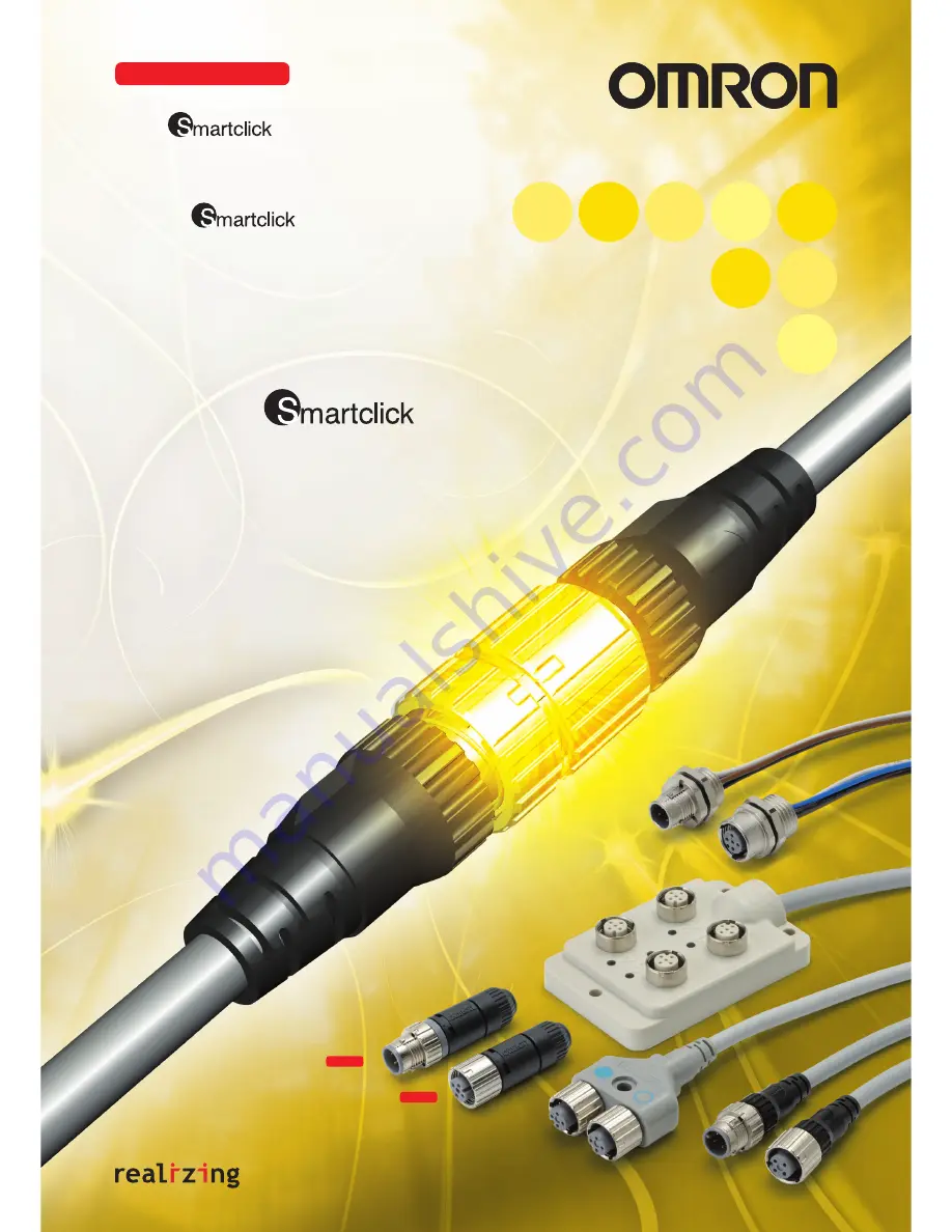
Round Water-resistant Connectors

Simple, Twist-and-Click Connection. 
Meet the Next-generation 
M12                  Connector!

XW3D

Connector Terminal  Boxes

Summary of Contents for M12 -

Page 1: ...to the Lineup Many Sensors for Easier Application XW3D XS5M XS5P N E W XS5G N E W XS5C XS5R XS5 XS5 Round Water resistant Connectors Simple Twist and Click Connection Meet the Next generation M12 Connector XW3D Connector Terminal Boxes ...

Page 2: ...it s connected Solution Solution Click Click Insert all the way in 1 8th of a turn An innovative new lock structure makes connection extremely simple The lock mechanism is internal so it will no longer become jammed by sputtered fluids or dust Also the use of a movable lock bolt makes it possible to connect the Smartclick XS5 to a screw type M12 connector XS5 Smartclick Socket Connector XS5 Smartc...

Page 3: ...ange 25 to 70 C Cable outer diameter mm Core sizes Crimping models Soldering models Screw on models 8 mm 7 to 8 mm 0 18 to 0 75 mm2 7 mm 6 to 8 mm 6 mm 5 to 6 mm Two types of con tacts are available 0 18 to 0 3 mm2 0 5 to 0 75 mm2 0 5 mm2 max 4 mm 4 to 5 mm 3 mm 3 to 4 mm Item Model XS5F H W R XS5M P XS5C G Con tacts Materials Phosphor bronze Brass Finish Nickel base 0 4 µm gold plating Fixtures N...

Page 4: ... Cable XS5W D42 81 F is warm gray Standard Cable XS5W D42 81 A Vibration proof Robot Cable XS5W D42 81 F Oil resistant Polyurethane Cable XS5W D42 81 P 40 7 L Cable length 44 7 6 dia M12 Straight straight L Cable length 32 3 28 3 6 dia M12 Angled angled L Cable length 28 3 44 7 6 dia M12 Angled straight 1 2 3 4 1 2 3 4 Terminal No Brown White Blue Black Cable color of core sheath Wiring Diagram fo...

Page 5: ...is model number legend to identify products from their model number When ordering use a mod el number from the table in Ordering Information XS5W D42 81 8 3 4 2 6 9 5 1 7 Cable specifi cations Cable length L m Straight straight Angled angled Minimum order UL Model Standard Cable 1 XS5W D421 C81 A 10 Yes 2 XS5W D421 D81 A XS5W D422 D81 A 3 XS5W D421 E81 A 5 XS5W D421 G81 A XS5W D422 G81 A 5 10 XS5W...

Page 6: ... XS5F D421 G80 F XS5F D422 G80 F 5 10 XS5F D421 J80 F XS5F D422 J80 F Oil resistant Polyurethane Cable 2 XS5F D421 D80 P XS5F D422 D80 P 10 5 XS5F D421 G80 P XS5F D422 G80 P 5 10 XS5F D421 J80 P XS5F D422 J80 P Straight 6 dia 40 7 L Cable length 50 30 5 M12 14 9 dia 1 2 3 4 Brown White Blue Black Terminal No Cable color of core sheath Wiring Diagram for 4 Cores 6 dia 25 3 28 3 L Cable length 50 30...

Page 7: ...0 F 5 XS5H D421 G80 F XS5H D422 G80 F 5 Oil resistant Polyurethane Cable 0 3 XS5H D421 A80 P XS5H D422 A80 P 10 2 XS5H D421 D80 P XS5H D422 D80 P 5 XS5H D421 G80 P XS5H D422 G80 P 5 44 7 6 dia L Cable length 50 30 5 M12 1 2 3 4 Brown White Blue Black Terminal No Cable color of core sheath L Cable length 6 dia M12 50 30 5 32 3 25 3 Wiring Diagram for 4 Cores Angled Straight Use this model number le...

Page 8: ...6 XS5G D4S1 XS5G D4S2 4 mm 4 to 5 XS5G D4S3 XS5G D4S4 3 mm 3 to 4 XS5G D4S5 XS5G D4S6 8 mm 7 to 8 XS5G D4S7 7 mm 6 to 7 XS5G D4S9 5 Screw on 6 mm 5 to 6 XS5G D5S1 4 mm 4 to 5 XS5G D5S3 3 mm 3 to 4 XS5G D5S5 8 mm 7 to 8 XS5G D5S7 7 mm 6 to 7 XS5G D5S9 14 9 dia 49 3 14 2 dia M12 XS5G D4C Crimping Model XS5G D42 Soldering Model Straight Connectors 37 7 14 9 dia 23 M12 XS5G D42 Soldering Model Angled ...

Page 9: ...size mm2 Model Minimum order 0 18 to 0 3 XS5U 3121 100 0 5 to 0 75 XS5U 3122 XS5U 312 Plug Pin 2 3 dia 2 dia C dia 1 5 1 dia B Slit A A special tool must be used for crimping For details refer to page 16 Dimensions Model Suitable core size mm2 Dimension mm No of slits A B C XS5U 3121 0 18 to 0 3 22 6 6 1 0 8 1 XS5U 3122 0 5 to 0 75 22 7 6 2 1 3 0 ...

Page 10: ... XS5C D4S5 XS5C D4S6 8 mm 7 to 8 XS5C D4S7 7 mm 6 to 7 XS5C D4S9 5 Screw on 6 mm 5 to 6 XS5C D5S1 4 mm 4 to 5 XS5C D5S3 3 mm 3 to 4 XS5C D5S5 8 mm 7 to 8 XS5C D5S7 7 mm 6 to 7 XS5C D5S9 XS5C D4C Crimping Model XS5C D42 Soldering Model Straight Connectors M12 43 4 14 9 dia 14 2 dia M12 31 8 14 9 dia 23 XS5C D4C Crimping Model XS5C D42 Soldering Model Angled Connectors 54 9 20 dia 14 9 dia 16 dia XS...

Page 11: ...e size mm2 Model Minimum order 0 18 to 0 3 XS5U 2221 100 0 5 to 0 75 XS5U 2222 XS5U 222 Socket Pin Slit 2 3 dia 2 dia C dia 1 5 B A A special tool must be used for crimping For details refer to page 16 Dimensions Model Suitable core size mm2 Dimension mm No of slits A B C XS5U 2221 0 18 to 0 3 16 7 6 1 0 8 1 XS5U 2222 0 5 to 0 75 16 8 6 2 1 3 0 ...

Page 12: ...S5R D426 5 XS5R D426 11 F Connectors on Both Ends Y Joint Plug Socket 1 2 3 4 4 3 2 1 1 2 3 4 CN2 CN1 1 4 3 2 1 4 3 2 1 4 3 2 1 4 3 2 1 4 3 2 1 4 3 2 1 4 3 2 1 4 3 2 45 5 4 6 dia 18 0 35 0 CN1 CN2 15 0 Blue marking 8 5 13 6 L Cable length 6 dia 44 7 Wiring Diagram XS5R D426 10 F Connectors on One Cable End Y Joint Socket 1 4 3 2 1 4 3 2 1 4 3 2 1 4 3 2 18 0 15 0 35 0 CN1 CN2 Blue marking 45 5 4 6 ...

Page 13: ...wn Black Blue 18 20 500 22 1 11 9 2 5 14 6 dia PG9 2 8 M12 17 18 10 3 XS5P D427 5 Panel mounting Sockets with Front Locks 2 3 4 1 M12 PG9 20 500 22 1 18 20 White Blue Brown Black 17 18 10 5 2 5 10 3 13 9 dia 2 8 Panel Cutout Dimension Panel thickness 1 to 4 mm 15 3 0 1 0 dia Pin number Color 1 Brown 2 White 3 Blue 4 Black Item Specification Specification UL1007 Nominal size AWG20 Configuration Num...

Page 14: ...9 500 22 8 18 17 White Brown Blue Black 18 20 10 2 8 10 3 20 2 3 4 1 XS5M D427 5 Panel mounting Plugs with Front Locks 1 4 3 2 PG9 M12 20 500 22 8 18 20 White Brown Blue Black 18 17 8 2 8 10 3 2 8 Panel Cutout Dimension Panel thickness 1 to 4 mm 15 3 0 1 0 dia Pin number Color 1 Brown 2 White 3 Blue 4 Black Item Specification Specification UL1007 Nominal size AWG20 Configuration Number of wires 21...

Page 15: ...e The pin block must not be extracted from the same Connector more than 3 times otherwise the proper degree of protection of the pin block or Connector will not be maintained Crimp Tool XY2F 0002 Locator XY2F 0003 5 4 3 2 1 8 7 6 R AISE TO RO T A T E SEL NO P U S H P O S I TIONER AND R O T A T E 9 0 T O I N S T A L L R O T A T E 9 0 TO INSTALL Tool in open position Tool in closed position XY2F 000...

Page 16: ...egree of protection of the connector will not be maintained Strip 14 mm of the Cable sheath and 4 mm of each core Make sure that each core is not damaged and its end strands are not spread out Mount the XY2F 0003 Locator to XY2F 0002 Crimping Tool both of which are sold separately and set the selector dial of the Crimping Tool to 6 for the XS5U 21 and to 7 for the XS5U 22 After mounting the crimpi...

Page 17: ...terminal Tighten the screw and then check visually to see if there is insulation between the cores Connect the cores to pins 1 to 4 When tightening the screws use the dedicated XW4Z 00B Screwdriver that matches with the screw slot dimensions 4 Inserting Pin Block Mount the cover to the pin block so that the triangle mark on the pin block will coincide with the triangle mark on the cover If the cov...

Page 18: ...el with a connector make sure that the connector plug is on the Sensor side and the connector socket is on the panel side i e the female pins are located on the power supply side Connecting the XS5 1 Connecting the XS5 Plug and Socket Align the projection on the plug cover with the polarity key on the socket then insert the plug all the way in Hold the knurled socket grip then insert the projectio...

Page 19: ...ree of Protection The degree of protection of Connectors IP67 is not for a fully watertight structure Do not the Connectors underwater Do not step on or place any objects on the Connectors Doing so may damage the Connectors General Precautions Do not pull excessively on the Connectors or cables Do not install the Connectors or cables in any way that would place a load directly on the mating sectio...

Page 20: ...21 MEMO ...

Page 21: ...A max Degree of protection IP67 IEC60529 Insertion tolerance 50 times min Lock strength Pulling 100 N 15 s Twisting 1 N m 15 s Cable holding strength 100 N 15 s Lock operating force 0 1 N m to 0 25 N m Ambient temperature range Operating 25 to 70 C Item Materials finish Contacts Brass nickel base 0 4 µm gold plating Fixtures Nickel plated zinc alloy Case PBT resin UL94V O light gray Bushing Rubber...

Page 22: ...old Separately XS2Z 22 Note 1 The XW3D XW3B XW3A comes with a dust cover Use the optional XS2Z 22 Waterproof Cover when an IP67 degree of protection is required 2 The XS2Z 22 connection is threaded Model No per box Material XS2Z 22 50 Brass with Ni plating 9 27 82 120 5000 10 100 73 4 5 27 Power indicator green LED Operation indicator red LED 13 5 6 5 9 9 33 54 6 9 dia 9 20 Indication of internal ...

Page 23: ... 4 2 3 1 5 4 2 3 1 5 4 2 3 1 5 4 2 3 1 5 4 2 3 1 5 4 2 3 1 5 4 2 3 1 5 4 2 3 Ground Green Yellow Negative power supply Blue Negative power supply Blue Positive power supply Brown Positive power supply Brown Positive power supply Brown Signal 1 White Signal 3 Yellow Signal 4 Gray Signal 5 Pink Signal 6 Red Signal 7 Black Signal 8 Purple 1 5 4 2 3 1 5 4 2 3 1 5 4 2 3 1 5 4 2 3 1 5 4 2 3 1 5 4 2 3 1 ...

Page 24: ...y not operate or the operation indicator may not light Always connect a load to the signal lines to operate a sensor or actuator Applicable Connectors Always mount a Waterproof Cover XS2Z 22 or Dust Cover XS2Z 15 to any unused connector on the Connector Terminal Box Power Supply and Operation Indicators The power supply indicator will be lit green while power is being supplied The operation indica...

Page 25: ... Sensing distance Model NPN output PNP output Through beam E3ZM CT61 M1TJ E3ZM CT81 M1TJ E3ZM CT62B M1TJ E3ZM CT82B M1TJ Retro reflective E3ZM CR61 M1TJ E3ZM CR81 M1TJ Diffuse reflective E3ZM CD62 M1TJ E3ZM CD82 M1TJ BGS reflective E3ZM CL61H M1TJ E3ZM CL81H M1TJ E3ZM CL62H M1TJ E3ZM CL82H M1TJ E3ZM CL64H M1TJ E3ZM CL84H M1TJ Sensing method Appearance Sensing distance Model NPN output PNP output T...

Page 26: ...M1TJ Retro reflective Side view Light ON E3T SR21 M1TJ E3T SR23 M1TJ Dark ON E3T SR22 M1TJ E3T SR24 M1TJ Side view Light ON E3T SR31 M1TJ E3T SR33 M1TJ Dark ON E3T SR32 M1TJ E3T SR34 M1TJ Diffuse reflective Flat Light ON E3T FD11 M1TJ E3T FD13 M1TJ Dark ON E3T FD12 M1TJ E3T FD14 M1TJ Convergent reflective Side view Light ON E3T SL11 M1TJ E3T SL13 M1TJ Dark ON E3T SL12 M1TJ E3T SL14 M1TJ Light ON E...

Page 27: ...U M18 E2E X7D1 M1TGJ U M30 E2E X10D1 M1TGJ U M8 2 Wire DC Polarity 1 2 Pin Specifications NC E2E X2D2 M1TGJ U M12 E2E X3D2 M1TGJ U M18 E2E X7D2 M1TGJ U M30 E2E X10D2 M1TGJ U Appearance Sensing distance Output configuration Operating mode Model M8 2 Wire DC Polarity 1 4 Pin Specifications NO E2E X2D1 M1TGJ M12 E2E X3D1 M1TGJ M18 E2E X7D1 M1TGJ M30 E2E X10D1 M1TGJ M12 2 Wire DC Polarity 1 4 Pin Spec...

Page 28: ... 4 Pin Specifications NO E2EZ X2D1 M1TGJ M18 E2EZ X4D1 M1TGJ M30 E2EZ X8D1 M1TGJ M12 2 Wire DC Polarity 3 4 Pin Specifications NO E2EZ X2D1 M1TJ M18 E2EZ X4D1 M1TJ M30 E2EZ X8D1 M1TJ Appearance Sensing distance Output configuration Operating mode Model M12 3 Wire DC PNP 1 4 3 Pin Specifications NO E2V X4B1 M1TJ M18 E2V X8B1 M1TJ M30 E2V X15B1 M1TJ M12 3 Wire DC NPN 1 4 3 Pin Specifications NO E2V ...

Page 29: ...MEMO 30 ...

Page 30: ...may be suitable for the products Outdoor use uses involving potential chemical contamination or electrical interference or conditions or uses not described in this document Nuclear energy control systems combustion systems railroad systems aviation systems medical equipment amusement machines vehicles safety equipment and installations subject to separate industry or government regulations Systems...

Page 31: ...08 Regional Headquarters OMRON EUROPE B V Sensor Business Unit Carl Benz Str 4 D 71154 Nufringen Germany Tel 49 7032 811 0 Fax 49 7032 811 199 OMRON ELECTRONICS LLC 1 East Commerce Drive Schaumburg IL 60173 U S A Tel 1 847 843 7900 Fax 1 847 843 8568 OMRON ASIA PACIFIC PTE LTD 83 Clemenceau Avenue 11 01 UE Square 239920 Singapore Tel 65 6835 3011 Fax 65 6835 2711 OMRON CHINA CO LTD Room 2211 Bank ...

Reviews: