


Chapter 7: Technical Specifications
relatively low voltage levels. You must take the necessary steps to prevent damage to the robot
system (such as by interposing a transformer). See
IEC
61131-4 for additional information.
7.7 EtherCAT Communications Specifications
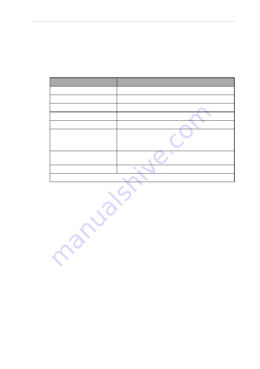
EtherCAT communications specifications are provided in the table below.
Figure 7-19. EtherCAT Communications Specification Description
Item
Specification
Synchronization
DC (Distributed Clock)
Physical Layer
100BASE-TX
Modulation
Baseband
Baud rate
100 Mbits/s
Topology
1
Line, daisy chain, and branching
Transmission media
Twisted-pair cable of category 5 or higher
Recommended cable: straight, double-shielded cable with
aluminum tape and braiding
Maximum transmission distance
between nodes
100 m
Communications cycle
2 ms, 4 ms
1
Wiring in a ring configuration is not possible.
7.8 Mounting Frame Specifications
The robot is designed to be mounted above the work area, suspended from a user-supplied
frame. The frame must be adequately stiff to hold the robot rigidly in place while the robot plat-
form moves around the workspace. You can either use the design provided or design a custom
support frame.
If you choose to design a custom frame, it must meet the following specifications:
Frame natural frequencies for stable robot operations:
l
Frequency > 25 Hz ( > 40 Hz for aggressive moves or heavy payloads)
l
Mounting surfaces for the robot pads must be within 0.75 mm of a flat plane.
If the surfaces are not within this tolerance, they should be shimmed.
IMPORTANT:
Failure to mount the robot within 0.75 mm of a flat plane will res-
ult in inconsistent robot motions.
The iCS-ECAT must be removable from the top of the frame and the inner and outer arm
travel envelopes must be considered. Refer to Arm Travel Volumes on page 120 for more
information.
22792-000 Rev. A
iX3 565 Robot with EtherCAT User’s Manual
135