


128
iX3 565 Robot with EtherCAT User’s Manual
22792-000 Rev. A
7.5 Performance Specifications
Stopping Time and Distance
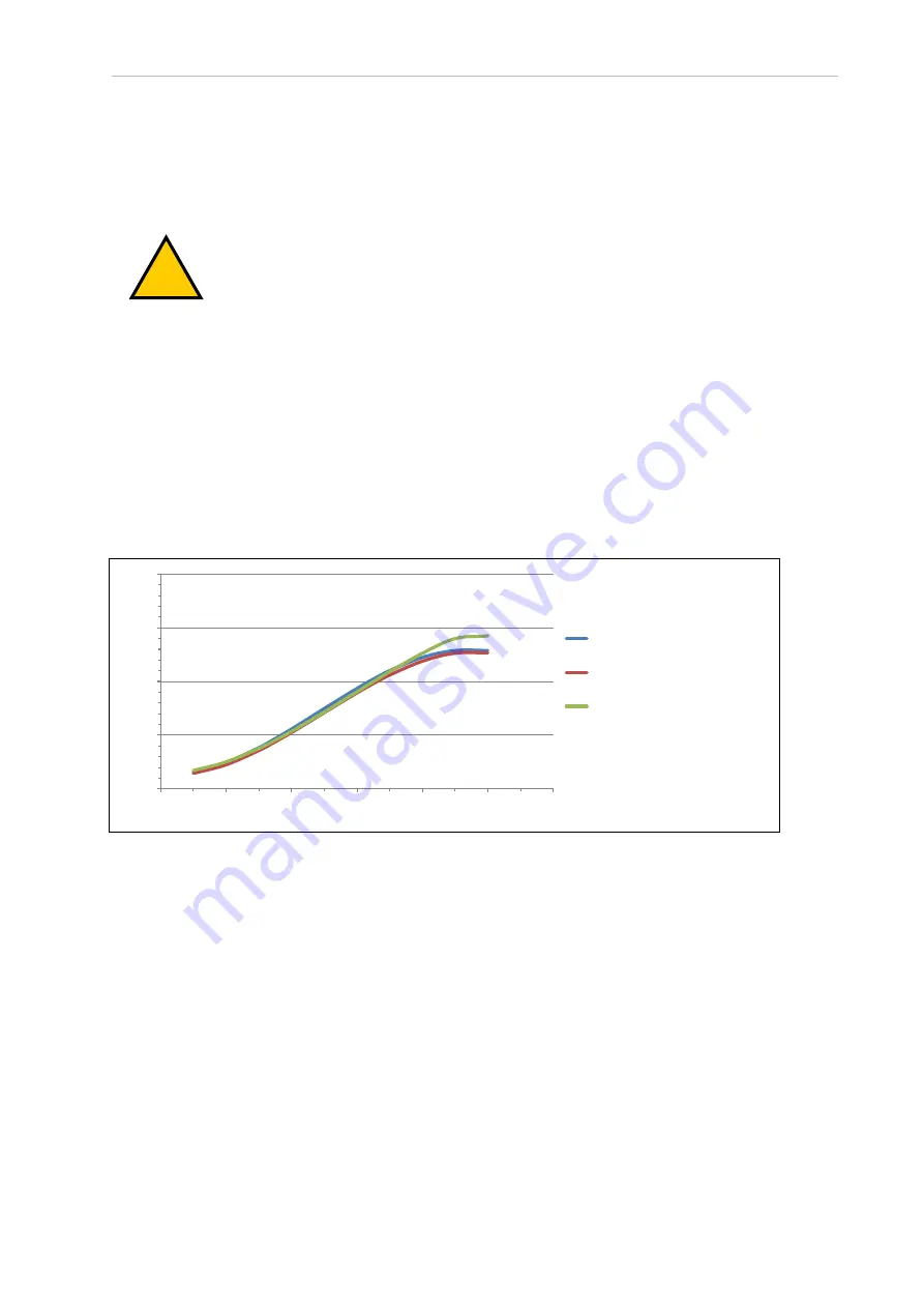
The following graphs present information required by Clause 7.2 n of ISO 10218-1. This inform-
ation should be used to calculate the safe distance needed when designing and installing safe-
guarding devices.
!
WARNING:
The stopping time and distance from initiation of a stop signal is
not negligible and must be taken into account when designing and applying
safeguarding devices.
The graphs show the time elapsed and distances traveled between the initiation of a stop sig-
nal and the cessation of all robot motion.
Stopping distances and times will not degrade as a result of either aging or normal use. Stop-
ping distance will vary only if there is an actuating mechanism failure, which may require
replacement of the failed component.
If you want to measure stopping distances and times on a system, contact your local
OMRON representative for more information.
NOTE:
Where lines overlap (and may not be visible) differences are not sig-
nificant.
0
100
200
300
400
0
20
40
60
80
100
120
Stopping Distance (mm)
Speed (%)
Payload 33%, 5.9 m/s max
Payload 66%, 5.8 m/s max
Payload 100%, 5.7 m/s max
Figure 7-7. Stopping Distance, X Axis Move (4 Axis Robot Type)