2
In
sta
llatio
n
a
nd
Con
nection
s
Part Names and Functions
FQ2 User’s Manual
29
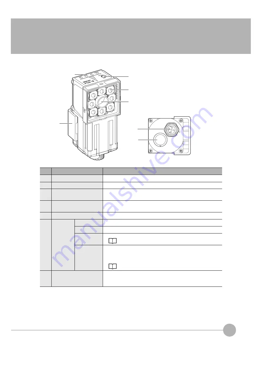
2-2 Part Names and Functions
FQ2-S
@@@@@@
-
@@@
(Sensors with Built-in Lighting)
No.
Name
Description
(1)
Lighting
LEDs for illumination
(2)
Camera lens
This lens can be focused.
(3)
I/O Cable connector
An FQ-WD or FQ-WU I/O Cable is used to connect the Sensor to the power
supply and external I/O.
(4)
Ethernet cable connector
An FQ-WN Ethernet Cable is used to connect the Sensor to external
devices such as PLCs, the Touch Finder, or computers.
(5)
Focus adjustment screw
Used to adjust the focus of the image.
(6)
Operation
indicators
OR
Lights orange when the overall judgement output (OR) signal turns ON.
ETN
Lights orange during Ethernet communications.
ERROR
Lights red when an error occurs.
BUSY
Lights green when the Sensor is executing a process.
* You can change the BUSY indicator to a RUN indicator.
This indicator is set by default to a BUSY indicator, but if you change it to a
RUN indicator, it will light green during operation.
Changing the Sensor’s BUSY Indicator: p. 231
(7)
Mounting Bracket
Used to mount the Sensor.
The Mounting Bracket can be attached to the front, left side, right side, or
back of the Sensor.
(2)
(3)
(5)
(1)
(6)
(7)
(4)
Summary of Contents for FQ2 Series
Page 1: ...User s Manual Smart Camera FQ2 Cat No Z326 E1 01A ...
Page 58: ...Setting Up Ethernet 56 FQ2 User s Manual MEMO ...
Page 90: ...Adjusting the Images That Were Taken 88 FQ2 User s Manual MEMO ...
Page 190: ...Adjusting Judgement Parameters during Operation 188 FQ2 User s Manual MEMO ...
Page 234: ...Functions Related to the System 232 FQ2 User s Manual MEMO ...
Page 404: ...Basic Troubleshooting 402 FQ2 User s Manual MEMO ...
Page 513: ...Index FQ2 User s Manual 511 Index 12 ...
Page 515: ......


