䝉䞊䝣䝔䜱䝷䜲䝖䜹䞊䝔䞁
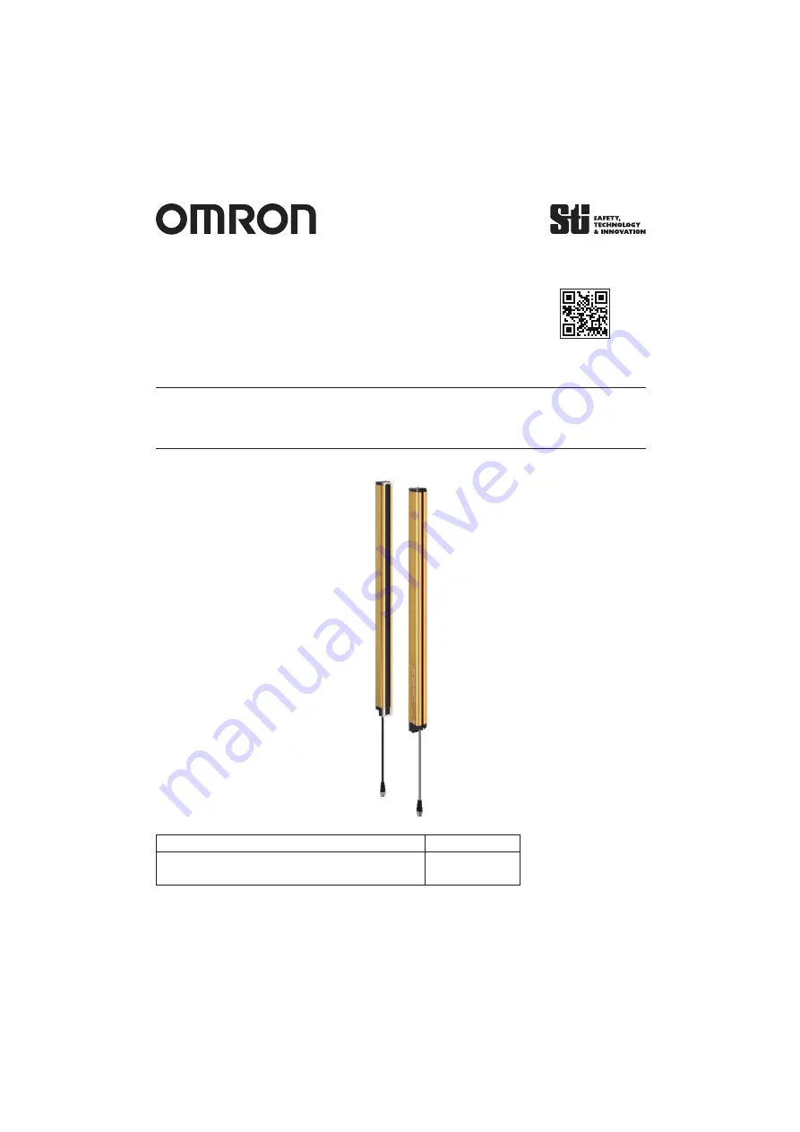
F3SG-4RA
䕕䕕䕕䕕
-25-02TS
© OMRON Corporation 2017 All Rights Reserved.
Original instructions
䜽䜲䝑䜽䜲䞁䝇䝖䞊䝹䝬䝙䝳䜰䝹
http://www.ia.omron.com/f3sg-r
䝬䝙䝳䜰䝹ྡ⛠
䝬䝙䝳䜰䝹␒ྕ
䝉䞊䝣䝔䜱䝷䜲䝖䜹䞊䝔䞁㻌㻲㻟㻿㻳㻙㻠㻾㻭䕕䕕䕕䕕㻙㻞㻡㻙㻜㻞㼀㻿㻌䝅䝸䞊䝈䝴䞊䝄䞊䝈䝬䝙䝳䜰䝹
㻿㻳㻲㻹㻙㻣㻞㻞
Page 1: ...F3SG 4RA 25 02TS OMRON Corporation 2017 All Rights Reserved Original instructions http www ia omron com f3sg r...
Page 2: ...02TS F3SG R F3SG R http www ia omron com f3sg r 1 1 2 2 3 2 4 SW 3 4 1 SW 3 4 2 3 5 4 5 1 EDM 24V 4 5 2 24V 4 6 5 6 1 F39 LGRA 5 6 2 F39 LGRTB 7 6 3 F39 LGRTB 2 8 6 4 F39 LGRTB 3 9 7 12 12 1 LED F3SG...
Page 3: ...2 F3SG 4RA 25 02TS 2 3 SW 3 4 5 12...
Page 4: ...3 F3SG 4RA 25 02TS 4 SW 4 1 SW SW F3SG R SW SW SW SW SW F3SG R SW F3SG R SW F3SG R 4 2 F3SG R M2 5 0 35N m A B 24V 0V...
Page 5: ...4 F3SG 4RA 25 02TS 5 5 1 EDM 24V 5 2 24V F39 JD BA F39 CN5 IEC60529 IP67 1 a 24V 2 b KM1 KM2 3 F39 JD RA L 4 F39 JD A 0V 24V 1 a 24V 2 F39 JD A 0V 24V F39 JD BA F39 CN5...
Page 6: ...5 F3SG 4RA 25 02TS 6 6 1 F39 LGRA mm 1 2 0240 1 C 2 1 C 4 D C 20 P 20 C 1 F 0240 1200 2 2 1000mm 1280 1920 3 1000mm...
Page 7: ...6 F3SG 4RA 25 02TS 1 2 3 3 0N m 4 3 0N m 15...
Page 8: ...7 F3SG 4RA 25 02TS 6 2 F39 LGRTB mm C 4 D C 20 G C 27 2 N1 N2 H C 38 N1 N2 I C 58 N1 N2 N1 0 30 N2 0 13 P 20 C F 0240 1040 2 0 1120 1920 2 1 1000mm...
Page 9: ...8 F3SG 4RA 25 02TS 6 3 F39 LGRTB 2 mm C 4 D C 20 G C 51 N1 N2 H C 54 N1 N2 I C 88 N1 N2 J C 106 N1 N2 N1 0 30 N2 0 13 P 20 C F 0240 1040 2 0 1120 1920 2 1 1000mm...
Page 10: ...9 F3SG 4RA 25 02TS 6 4 F39 LGRTB 3 mm C 4 D C 20 G C 39 5 N1 N2 H C 65 N1 N2 I C 84 N1 N2 N1 0 30 N2 0 13 P 20 C F 0240 1040 2 0 1120 1920 2 1 1000mm...
Page 11: ...10 F3SG 4RA 25 02TS 1 2 2 F3SG R 1 3 0N m 3 4 1 1 2 2 3...
Page 12: ...11 F3SG 4RA 25 02TS 5 3 0N m 6 7 3 0N m 22 5 15 1 2...
Page 13: ...ron com f3sg r LED LOCKOUT 1 TOP BLANK CFG EDM INTERNAL ON OFF COM BTM LONG POWER LOCKOUT 2 POWER LOCKOUT STB SEQ http www ia omron com f3sg r Web 0120 919 066 8 00 21 00 365 FAX Web PHS IP 055 982 50...
Page 14: ...A 25 02TS OMRON Corporation 2017 All Rights Reserved Original instructions 9309529 9C Quick Installation Manual http www ia omron com f3sg r Document Title Cat No Safty Light Curtain F3SG 4RA 25 02TS...
Page 15: ...in 24V Active not used 4 6 Mounting and Beam Alignment 5 6 1 Mounting with Free Location Brackets F39 LGRA 5 6 2 Mounting with Top Bottom Brackets F39 LGRTB 7 6 3 Mounting with Top Bottom Brackets F39...
Page 16: ...erminal Beam center line mark Rotary Switch Functional earth terminal 1 Test indicator Green 2 LONG indicator Green 3 Power indicator Green 4 Lockout indicator Red 1 TOP indicator Blue 2 NPN indicator...
Page 17: ...Function with End Cap F3SG R series has End Cap to configure the function at the opposite end from the power cable of the emitter Configure the function before installing the F3SG R in your site Make...
Page 18: ...contact if External Test is used 2 Connect a lockout reset switch N C contact to this line in series with the KM1 and KM2 if Lockout Reset is used 3 The F39 JD RA L Single Ended Cable for Emitter Oil...
Page 19: ...equired to mount either one of emitter and receiver 2 Mounting an emitter or receiver with one bracket is possible for the model of protective height of 0240 In this case locate this bracket at half t...
Page 20: ...N m recommended The angle adjustment range of the Free Location Brackets is 15 Backside mounting Side mounting M5 M6 M5 M6 Mounting Screw hexagon socket head cap screw M4 22 Bracket 1 Bracket 2 Mount...
Page 21: ...ght 2 M5 or M6 2 M5 or M6 Unit mm Backside mounting Refer to the user s manual for dimensions of side mounting The number of brackets required to mount either one of emitter and receiver Dimension C 4...
Page 22: ...ve height 2 M5 or M6 2 M5 or M6 Unit mm Backside mounting Refer to the user s manual for dimensions of side mounting The number of brackets required to mount either one of emitter and receiver Dimensi...
Page 23: ...ht 2 M5 or M6 2 M5 or M6 2 M5 or M6 Unit mm Backside mounting Refer to the user s manual for dimensions of side mounting The number of brackets required to mount either one of emitter and receiver Dim...
Page 24: ...ting Screw of the Intermediate Bracket Then fit the F3SG R housing to the bracket Top Bottom Bracket 1 Top Bottom Bracket 1 Top Bottom Bracket 3 1 1 2 2 3 Top Bottom Bracket 3 Top Bottom Bracket 2 Top...
Page 25: ...ustment range is 22 5 when using the Top Bottom Brackets only The angle adjustment range is 15 when using the Top Bottom Brackets and Intermediate Bracket together Mounting Screw Alignment Screw hexag...
Page 26: ...lete determination of the suitability of the Product in combination with the end product machine system or other application or use Buyer shall be solely responsible for determining appropriateness of...