Device description
Section 1-2
4
1-2-2 Device model
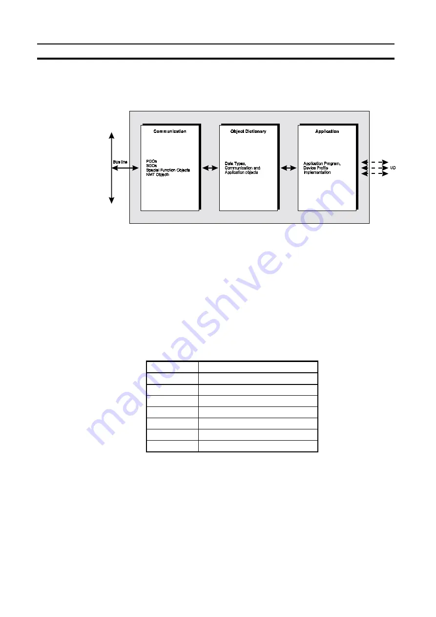
The following figure shows the general model of a CANopen device.
A CANopen device can be divided in three parts:
•
Communication
interface
•
Object
dictionary
•
Application
interface
These three parts are discussed in the following sections, starting with the
core of a device, the object dictionary.
1-2-2-1 Object dictionary
The core of every CANopen device is its object dictionary. The structure of
this dictionary is as follows:
Index (hex)
Objects
0000
Reserved for future use
0001 ~ 009F
Data type definitions
00A0 ~ 0FFF
Reserved for future use
1000 ~ 1FFF
Communication Profile Area
2000 ~ 5FFF
Manufacturer Specific Profile Area
6000 ~ 9FFF
Standardised Device Profile Area
A000 ~ FFFF
Reserved for future use
Object oriented
Index
Sub-index
A CANopen device is organised in an object-oriented manner. All objects are
accessed via an index number, which is a 16-bit value ranging from 0000h to
FFFFh.
'Simple variable' objects are accessed directly by their index.
Elements of 'complex variable' objects, like records or arrays, are accessed
by the index number and an 8-bit sub-index. This principle is shown in the
following example.
Summary of Contents for C200HW-CORT21-V1
Page 2: ...C200HW CORT21 V1 CANopen Slave Unit OPERATION MANUAL OMRON Cat No W904 E2 2 ...
Page 3: ......
Page 4: ......
Page 5: ......
Page 6: ...C200HW CORT21 V1 CANopen Slave Unit Operation Manual Produced June 2001 ...
Page 7: ...iv ...
Page 9: ...vi ...
Page 13: ...x ...
Page 47: ...Performance Section 2 3 30 ...
Page 85: ...Control and Status area Section 4 3 68 ...
Page 113: ...Flow diagrams Section 6 6 96 ...
Page 123: ...Maintenance Section 7 3 106 ...
Page 133: ...116 ...
Page 135: ...118 ...
Page 139: ...122 ...
Page 141: ......


