1 Preparation
1-4 Name of each part
BU150R
18
1-4 Name of each part
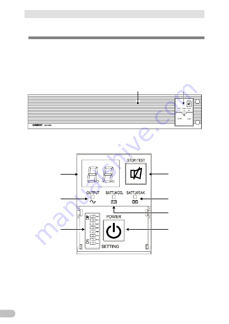
This section describes the name of each part of the UPS.
For information on the function of each part, refer to “2 Installation and connection
and “3 Check and start operation” (P.33) that provides the details.
■
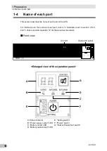
Front view
Air vent
Operation panel
A
B
E
G
D
C
F
A: Status indicator
B: “Power supply output” LED
C: “Battery mode” LED
D: “Battery replacement” LED
E: “Setting switch”
F: “Power” switch
G: “Buzzer Pause/Test” switch
<Enlarged view of the operation panel>
Summary of Contents for BU150R
Page 22: ...2 Installation and connection 2 1 Installation BU150R 22 Incorrect Positions...
Page 92: ...7 How to use option cards 7 3 SNMP Web card BU150R 92 7 3 SNMP Web card LAN 10 100...
Page 102: ...10 References 10 2 Dimensions BU150R 102 Stand for vertical layput 200 200 70 50 70 50...
Page 103: ...10 References 10 2 Dimensions BU150R 103 10 Rubber feet 23 25 405 50 40 358 40 3...
Page 104: ...10 References 10 2 Dimensions BU150R 104 Using Ear brackets 44 5 22 0 13 5 455 25 465...


