


80-J4866-2 Rev. G
MAY CONTAIN U.S. AND INTERNATIONAL EXPORT CONTROLLED INFORMATION
A-13
Wiring Diagrams and Charts
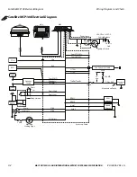
Radio Connector Pin Callouts
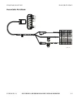
Radio Connector Pin Callouts
Front Drivers Side
Speaker Wire (B6)
Note: Connector tabs
on this side
06AAA_179A
Front Drivers Side
Speaker Wire (B5)
1
2
3
7
8
4
1
2
3
5
7
8
4
6
5
6
Notches
PIN
SIGNAL
A1
A2
A3
A4
A5
A6
A7
A8
N/C
N/C
PARK LIGHTS
IGN CONTACT
PWR ANT OUTPUT
PWM/ANALOG DIM
BATTERY - MAIN
GROUND
PIN SIGNAL
B1
B2
B3
B4
B7
B8
RR + SPEAKER
RR - SPEAKER
RF + SPEAKER
RF - SPEAKER
LR + SPEAKER
LR - SPEAKER
B5
B6
LF + SPEAKER
LF - SPEAKER
A
B
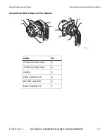
Common Radio and Harness


