background image

© 2010 Omnicell, Inc.

OmniTT/AnesthesiaTT Installation and Service Guide

/

67-2024 Rev D

1-1

Electronics Tray

Introduction

This section will give detailed instructions on the proper way to replace specific parts within the 
CT PC Sled, also known as the electronics tray. To complete any of these procedures, first ensure 
that the sled has been unplugged from any power outlet.

Tools List

The following tools are required to install the Electronics Tray:

„

T8 Torx Driver

„

T10 Torx Driver

„

T15 Torx Driver

„

9/64” Allen wrench

Removal Procedure 

LCD Screen

1. Perform a graceful shutdown of the electronics tray.

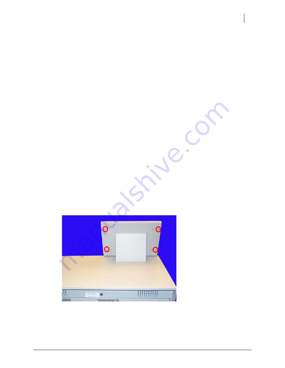
2. Remove the four oute

screws

 that secure the LCD bezel to the cabinet.

Use a Torx T10 screwdriver.

Figure 1-1.

Remove the Four Outer Screws

3. Remove th

front bezel

.

Summary of Contents for AnesthesiaTT

Page 1: ...OmniTT AnesthesiaTT Installation and Service Guide 67 2024 Rev D...

Page 2: ...1201 Charleston Road Mountain View CA 94043 650 251 6100 www omnicell com Omnicell and the Omnicell design mark OmniBuyer OmniCenter OmniRx OmniSupplier SafetyMed SafetyPak SafetyStock and Sure Med a...

Page 3: ...8 Remove the Electronics Tray 1 9 Remove the PowerCom2 tray from the OmniRx TT 1 11 Install the PowerCom3 CT PC Tray 1 11 Replace the cables 1 12 Frames and Wireways 2 1 Introduction 2 1 Tools List 2...

Page 4: ...OmniTT AnesthesiaTT Installation and Service Guide 67 2024 Rev D 2010 Omnicell Inc iv Table of Contents Feedback Form FB 1...

Page 5: ...y of these procedures first ensure that the sled has been unplugged from any power outlet Tools List The following tools are required to install the Electronics Tray T8 Torx Driver T10 Torx Driver T15...

Page 6: ...the flat panel cable 2 Set the lid back down 3 Remove the four inner screws at the back of the console lid Figure 1 2 Remove the Four Inner Screws 4 Remove the LCD assembly from the LCD housing Speak...

Page 7: ...speaker in place Use a Torx T10 screwdriver Figure 1 4 Remove the two screws that secure the speaker 5 Disconnect the speaker from the console top Printer 1 Perform a graceful shutdown of the electro...

Page 8: ...paper from the printer Push the platen lever to the left to set it to the disengage position Figure 1 6 Turn the Platen Lever to the Left and Remove the Paper 4 Remove the four screws two on each side...

Page 9: ...moval Procedure 6 Remove the four screws that secure the lower assembly to the frame Figure 1 8 Remove the Screws that Secure the Lower Assembly 7 Disconnect the printer ribbon cable and the printer d...

Page 10: ...24 Rev D 2010 Omnicell Inc 8 Remove the printer Figure 1 10 Remove the Printer Printer PC Card 1 Remove the four screws that secure the PC card to the frame Figure 1 11 Remove the Screws that Secure t...

Page 11: ...Electronics Tray 1 7 Removal Procedure Keyboard 1 Remove the 14 nuts that secure the keyboard cover to the tray Figure 1 12 Remove the nuts that secure the keyboard cover to the tray 2 Remove the keyb...

Page 12: ...tabs through the holes on the keyboard 2 Keeping the keypad upright reach underneath the keyboard and gently pull the tabs until the elastomer rests snugly on the keyboard 3 Remove any bubble or ripp...

Page 13: ...Guide 67 2024 Rev D Electronics Tray 1 9 Electronics Tray Electronics Tray 1 Disconnect the LAN cable and the AUX cables from the rear of the TT cabinet Figure 1 15 Location and labels for LAN and AU...

Page 14: ...es from tray only a LCD data cable b Contrast cable c Inverter backlight cable d Touch screen data cable e Keyboard cable f Speaker cable g Card reader cable if applicable not shown h Fan power cable...

Page 15: ...orward Figure 1 17 Lift and remove the CT PC Tray from the Omni TT 2 Lift the rear of the tray and twist slightly until the front tabs clear the frame 3 Remove the old electronics tray PowerCom3 CT PC...

Page 16: ...able to the J10 of the PowerCom3 Board Figure 1 19 Connect the Wireway Cable to J10 of the PowerCom3 Board 2 Connect the printer cable to J27 on the motherboard Figure 1 20 Connect the Printer Cable t...

Page 17: ...lectronics Tray 1 13 Electronics Tray 4 Connect the speaker cable to port J45 on the motherboard Figure 1 21 Connect the Speaker Cable to J45 of the Motherboard 5 Connect the keyboard cable to port J4...

Page 18: ...t to the touch screen data cable red wire to red wire b Wrap the joined connectors with electrical tape to ensure that the cables do not become disconnected c Connect the touch screen data cable exten...

Page 19: ...o J37 on the motherboard Figure 1 26 Connect the LCD Data Cable to J37 of the Motherboard 10 If a card reader is present and needs to be reconnected a Connect the card reader serial cable to J47 on th...

Page 20: ...out in this procedure 1 Lift and prop up the lid if it is not already open 2 Disconnect all console cables 3 Remove the console 4 Replace the cable cover bracket with the new wider one using three scr...

Page 21: ...n an Omni TT is removable and the SPC board contained in the wireway is also replaceable Tools List The following tools are required to perform the procedures in this chapter Torx T8 driver Torx T10 d...

Page 22: ...move the screws on either side of the transport handle using a Torx T25 screwdriver Figure 2 2 Remove the two screws securing the transport handle 6 Push the transport handle toward the rear of the ca...

Page 23: ...the SPC board 8 Remove the SPC board from the wireway Manual Override Cable Removal 1 Perform a graceful shutdown of the electronics sled 2 Remove the manual override cover 3 Remove all three drawers...

Page 24: ...Inc 9 Remove the four screws that secure the printer support bracket Figure 2 5 Remove the four screws that secure the printer support bracket to the frame 10 Remove the bracket 11 Remove the two scre...

Page 25: ...nual Override Cable 12 Remove the red handle on the front of the manual override cable Figure 2 7 Remove the red handle on the manual override cable 13 Remove the nut that secures the manual override...

Page 26: ...frame Figure 2 10 Loosen the nut that secures the cable to the frame anchor 16 Pull the cable from the anchor on the back of the frame 17 Pull the cable out from inside the TT cabinet Replacement 1 F...

Page 27: ...e red handle 8 Replace the two screws that secure the manual override cable to the inside of the front of the frame 9 Replace the printer support bracket 10 Replace the thermal printer paper and the s...

Page 28: ...rix drawers to the required number of bins The matrix drawers can be lit with guiding light technology OLMD or can come unlit OMD The lit matrix drawers are configurable up to a maximum of 24 bins and...

Page 29: ...ers ensure that the layout of each drawer has been approved by the customer 2 Break the divider tabs according to the customer design and trim away excess plastic to ensure a snug fit in the drawer 3...

Page 30: ...snap into the bottom of the drawer and the sides of each bin liner quadrant 4 Use the gray circular labels provided with the kit to cover any un used divider slots in the bin liner 5 Insert the light...

Page 31: ...r right corner of the drawer would be Bin 7 the bin in the upper left corner would be Bin 49 and the bin in the upper right corner would be Bin 85 Figure 3 3 Matrix drawer labelling system Once a bin...

Page 32: ...rame 6 Line up the rail with the screw holes on the front of the frame and replace the screws 7 Connect the drawer controller cable to the drawer controller board at the rear end of the drawer 8 Secur...

Page 33: ...e drawer controller cable between the two ends of the drawer controller cable clamp 13 Secure the pharmacy drawer controller cable clamp and the drawer controller cable to the pharmacy drawer with the...

Page 34: ...7 Removal Procedure 3 Pull the manual override lever and open the desired pharmacy drawer Figure 3 8 Pull the manual override lever 4 Remove the two screws securing the drawer controller cable cover...

Page 35: ...010 Omnicell Inc 5 Remove the cable clamp and disconnect the cable Figure 3 10 Remove the controller cable 6 Push the release levers on either side of the drawer up or down to release the drawer Figur...

Page 36: ...l 1 8 replacement 1 8 electronics tray 1 9 tools list 1 1 F frame 2 1 K keyboard removal 1 7 replacement 1 8 L LCD assembly 1 2 LCD screen 1 1 lid locking 3 1 sensing 3 1 M manual override cable repla...

Page 37: ...OMNIRX Printer platen lever part of MFG ASSY PRINTER OMNIRX Printer Manual Override Cable printer to cover screws part of MFG ASSY PRINTER OMNIRX Printer printer to frame screws part of MFG ASSY PRIN...

Page 38: ...SION MINIMAG CARD READER OMNIRX Electronics Tray 42 7095 fan power cable CABLE ASSY 2 FAN 92MM 12VDC OMNIRX Electronics Tray 51 2059 transport handle HANDLE TRANSPORT HALF CELL Wireway 51 2064 overrid...

Page 39: ...ER RX ACCURIDE C3834 156 1 SLIDE OUTER HALF SNAP IN ACCURIDE C3820 332 20L SLIDE INNER HALF DRAWER RX SHORT ACCURIDE C3834 156 2 Installation Procedure 94 6080 transport handle screw SCREW BHCS 1 4 20...

Page 40: ...ur input so we can continue to improve our publications Please send us your feedback Did this document meet your needs If so please let us know what we re doing right If not please provide specific fe...

Page 41: ......

Reviews: