


Bode 100 - Information
Detailed Functional & Calibration Check of Bode 100
Page 18 of 21
Smart Measurement Solutions
Smart Measurement Solutions
®
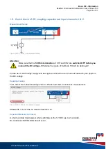
1.9 Quick check of AC coupling capacitors at input channels 1 & 2
Measurement Setup:
Figure 39: DC-Block - measurement setup
Attention
:
Make sure that the
50 Ohm termination
of CH1 and CH2 are
switched OFF before you
connect the DC voltage.
Otherwise the inputs of the Bode 100 will be destroyed!
Please use a DC Voltage Supply with low ripple and noise to avoid overload caused by the ripple on
the DC voltage.
Equipment setup:
First, select the
measurement type “Gain / Phase” and start a continuous measurement.
Figure 40: DC- Block
– measurement type
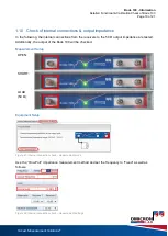
Afterwards, connect the 12 VDC and switch it on.
Expected Measurement result:
A short overload might appear when switching on the 12 VDC (up to 2 seconds).
No continuous OVERLOAD should occur.