


Configur
Configur
Configur
Configur
Configura
aa
a
ation
tion
tion
tion
tion
Configuration may be performed with a transmitter on-line or off-line.
When a transmitter is on-line, the upload and download icons will be
distinctly black. If no transmitter is on-line, those icons will be grey.
1. Upload
Current configuration from the transmitter
2. Configure
•
If the current “Sensor Type” does not match the application, click
on the “Sensor Selection” box then select the appropriate “tab” at the
top of the “Input Sensor Selection” screen.
•
Make one selection from the “Input Connection” and “Type” boxes
(if offered) for the selected sensor type. Leave the “Mode” as “Stan-
dard” or the “Transfer Function” as “Linear” for now. Click the “OK”
button to return to the Configuration Screen.
•
Select the Engineering Units (from the pull down menu), enter the
“Zero Scale” and “Full Scale” values and the “Burnout” mode
(transmitter to go above full scale or below zero scale upon input
failure).
•
Click the "
Set to Optimal
" button to optimize the
transmitter's filtering.
3. Download
New configuration to the transmitter.
Calibr
Calibr
Calibr
Calibr
Calibra
aa
a
ation
tion
tion
tion
tion
To calibrate the transmitter, connect a 24VDC power supply, a 250
Ω
load
and multi-meter (in milliamp mode) in series to the transmitter's output.
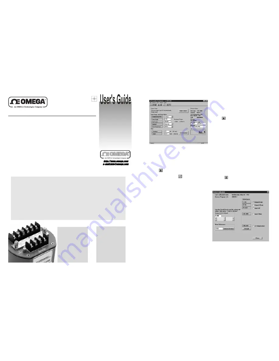
1. Upload
2. Click on the Calibration Icon
3. Output Calibration:
Select "
Output 4mA
", enter the mA reading from
the meter into the dialog box and click "Send to Device." Repeat for 20mA
calibration.
4A.
Input Calibration Models XXXXX-X000
(e.g. TX787-0000):
Provide a precision 100.00mV source to the transmitter, select "
Input mV
"
on the Device Calibration screen, wait for the on-screen display to settle,
then click "Send to Device." Repeat the procedure, substituting a 300.00
Ω
input (4-wire connection) and selecting "
Input Ohms.
"
4B. Input Calibration Models XXXXX-X001
(e.g. TX787-0001):
Provide a precision 300.00mV source to the transmitter, select "
Input
mV
" on the Device Calibration screen, wait for the on-screen display to
settle, then click "Send to Device." Repeat procedure, substituting a 15.00
Volt input and selecting "
Input Volts
", and substituting a 50mA input,
selecting "
Input mA.
" Note that the input terminals are different for each of
the signal levels.
5.
To calibrate the cold junction compensation reference, select
“Tem-
perature,”
enter the nominal ambient temperature in the dialog box, set
the input simulation type to match the input simulator (i.e., type J thermo-
couple), verify that the simulator is set to the proper value, then click “Send
to Device.”
6. Click “Close.”
A message in the lower left corner of the screen will
indicate the progress of the download and finally that the download has
been successfully completed.
1. Install the Configuration and Calibration software
Run “setup.exe” on the distribution diskette and follow the on-screen instructions.
Note: the software contained on the distribution diskette runs under Windows 95 and Windows NT.
If you are running Windows v3.1, contact Omega Engineering.
2. Connect the Communications Adapter to the computer and transmitter.
3. Identify the serial port to which the Adapter is connected.
Select “Options” from the menu bar, then click “Communications” and select the correct COMM port from the pull-
down menu. Note that if you change the serial port you must exit the software and restart
it with the correct setting.
4. Configure the transmitter.
What you will need:
Calibration
• PC
• Communications Adapter
• Transmitter
• Multimeter
• 24VDC power supply
Configuration
• PC
• Communications Adapter
• Transmitter
Intr
Intr
Intr
Intr
Intr oduction
oduction
oduction
oduction
oduction
Models TX787 and TX788 are microprocessor-based 2-wire transmitters that feature high accuracy and
high long-term stability. Setting the new standard in ease of setup, these transmitters feature
PC-Only™
configuration technology. The unique Communications Adapter provides a fully isolated serial interface
and power source,
allowing the transmitter to be configured with a “
PC-Only
” - no external power
supply, calibrator or meter is required!
Quic
Quic
Quic
Quic
Quick Star
k Star
k Star
k Star
k Star ttttt
Before beginning the process of setting up the transmitter, it is important to understand the difference between
calibration
and
configuration
. The transmitter’s precision references (4 and 20 milliamps out; resistance,
voltage and current as appropriate; and a thermal reference) are
calibrated
at the factory and may be adjusted
later if necessary.
Configuration
is the process of defining the sensor type and range in engineering units.
Configuration
is performed by connecting the transmitter to a PC and running the configuration software.
Because the Communications Adapter provides power to the transmitter’s microprocessor, it is not necessary to
provide any external power to the transmitter in order to configure it.
PC-Only Programmable Transmitter


