

Using This Quick Start Manual
Use this Quick Start Manual to set up your controller
and begin operation. Information is provided on how to:
¥
Connect ac power
¥
Connect the RTD
¥
Set basic options for operation
For complete information on all setup options, see the
OperatorÕs Manual.
Before You Begin
In addition to the meter and the related parts, you will
need the following items to set up your meter:
¥
ac power, as listed on meterÕs ID/Power Label
¥
RTD
¥
1
Ú
8
Ó flat blade screwdriver
Mount the Meter
1.
Cut a panel opening
using the dimensions
shown here.
2.
Position the meter in
the opening, making
sure the front bezel is flush with the panel.
Connect ac Power
Warning: Do not connect ac power to your meter
until you have completed all input and output
connections. Failure to do so may result in injury!
1.
Remove the panel at the back of the meter.
2.
Locate the TB1 connector.
3.
Insert the correct wire in each terminal and tighten
the lockdown screws. Tug gently on the wires to
verify connections.
Main ac Power Connections
To:
Take This Action
Select a value
1. Press
䊳
/MAX
. to display
for that submenu
the option you want.
function.
2. Press
MENU
to select it.
The message
STRD
quickly
flashes, indicating that the
selection has been stored in
memory. Then the next
menu function displays.
Go back to the
Press
RESET
once.
previous menu
function.
Exit the meter
¥ Press
RESET
twice. The
Configuration
reinitializes (displays
RST
,
Menu.
then
RTD
). When the
temperature displays, the
meter is back in run mode.
¥ Optionally, you can press
MENU
to move through all
the menu functions until the
meter reinitializes.
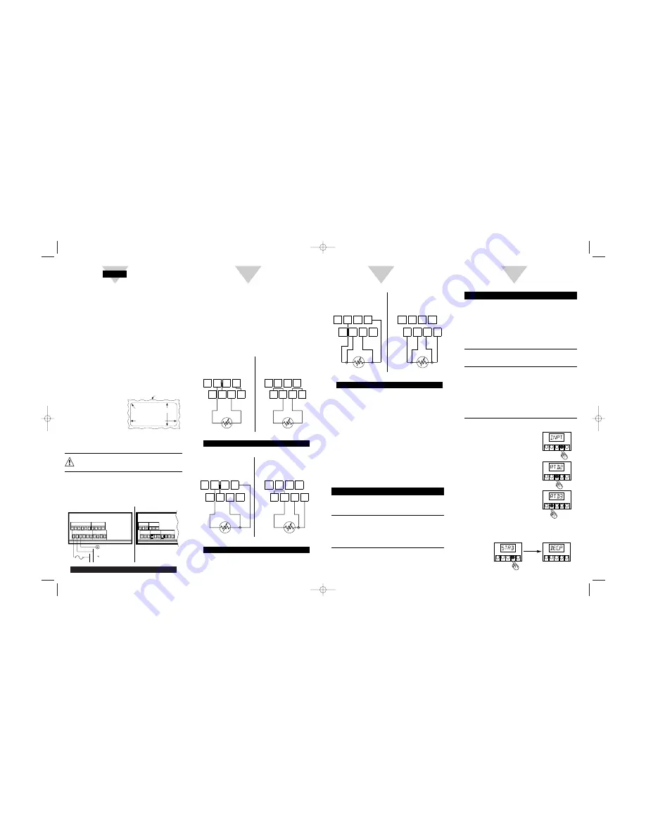
To Set the RTD Type:
1.
Press
MENU
until the meter
displays:
2.
Press
䊳
/DEV
. The meter
displays:
3.
Press
䊱
/MAX
until the
RTD
for your installation is shown.
¥ RTD.2 is for a 2-wire RTD
¥ RTD.3 is for a 3-wire RTD
¥ RTD.4 is for a 4-wire RTD
4.
Press
MENU
to select the RTD shown. The
meter displays:
4-Wire RTD Input Connection
Turn on the Meter
1.
Apply ac power to the meter. The meter initializes,
flashing RST then RTD on the front panel. Then
the temperature should appear.
2.
Verify that a temperature is displayed. If not:
¥
Remove ac power
¥
Verify the TB1 power connections
¥
Check your power source
¥
Apply ac power again
Configure the Meter
To configure the meter, use the buttons on the front
panel.
To:
Take This Action
Display the
Press the
MENU
button.
Configuration
The first function on the
Menu.
menu, INPT, displays.
Select the
1. Press
MENU
until the
sub-menu
function you want is shown.
(a function you
2. Press
䊳
/DEV
.
want to perform).
The information you can change
begins to flash.
8
VERSION #1
RTD
7
+S
+E
5
1
6
2
3
TB2
+E1
-S
-R
+R
8
4
+S1
RTD
VERSION #2
TB2
5
1
6
2
7
3
4
-E1
-S1
Connecting the RTD
1.
Locate the TB2 connector on the rear of the
meter.
2.
Attach the RTD wires, referring to the appropriate
diagram below and tighten down lockdown
screws.
3.
Tug gently on the wires to verify the connections.
4.
Replace the panel at the back of the meter.
2-Wire RTD Input Connection
3-Wire RTD Input Connection
VERSION #2
+S1
TB2
VERSION #1
1
-R
+S
3
+E
2
5 6
TB2
+R
4
7 8
+E1
1
5
2
-S1 -E1
RTD
6
3
7
4
8
-S
RTD
VERSION #2
+S1
TB2
VERSION #1
1
-R
+S
-S
3
+E
2
5 6
TB2
+R
4
7 8
+E1
1
5
2
-S1 -E1
RTD
6
3
7
4
8
RTD
START HERE
2
3
4
45,00 + 0,61/-0,00
(1.772 + .024/Ð.000)
92,00 + 0,81/Ð0,00
(3.622 + .032/Ð.000)
PANEL THICKNESS
1,5
R(.06)
4 PLCS
6,4 (.25) MAX
0,8 (.03) MIN
NOTE: Dimensions in Millimeters (Inches)
SINGLE RTD MODEL
NOT AVAILABLE FOR
TB2 PINS 1 THRU 4
VERSION #2
TB1
LINE
NEUTRAL
10 11 12
FUSE
AC POWER
EARTH
GROUND
TB1
VERSION #1
TB2
TB2
8
9
7
8
7
6
5
6
5
4
3
2
1
4
3
2
1
10 11 12
8
9
7
8
7
6
5
6
5
4
3
2
1
䊱
䊳
SETPTS
/DEV
MENU
RESET
/MAX
䊱
䊳
SETPTS
/DEV
MENU
RESET
/MAX
䊱
䊳
SETPTS
/DEV
MENU
RESET
/MAX
䊱
䊳
SETPTS
/DEV
MENU
RESET
/MAX
䊱
䊳
SETPTS
/DEV
MENU
RESET
/MAX
12504ML-98A_CN1000-RTD_OMG.qxd 8/13/99 11:29 AM Page 1


