


omega.com
e-mail: [email protected]
For latest product manuals:
omegamanual.info
User’s Guide
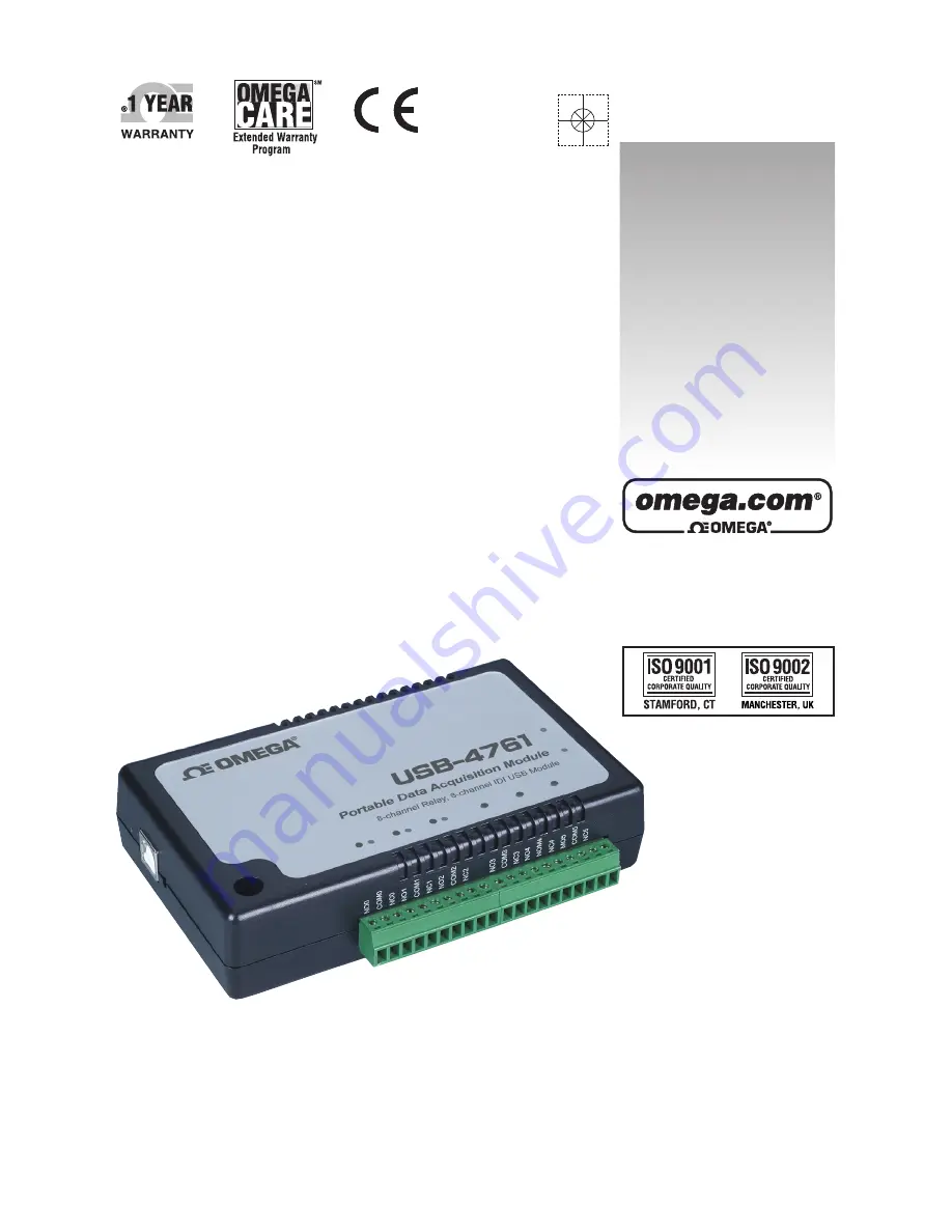
USB-4761
8 Channel Relay/Isolated DI
USB Data Acquisition Module
Shop online at
Summary of Contents for USB-4761
Page 3: ...USB 4761 8 channel Relay Isolated DI USB Data Acquisition Module User Manual...
Page 10: ...Figure 1 1 Installation Flow Chart 5 Chapter1...
Page 28: ...Figure 3 1 I O Connector Pin Assignment 23 Chapter3...
Page 32: ...A 2 Specifications...
Page 35: ...USB 4761 User Manual 30...
Page 36: ...B 2 Function Block...
Page 37: ...Appendix B Function Block USB 4761 User Manual 32...


