background image

DMTA-10040-01EN, Rev. E, February 2018

Control Functions

89

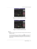
TOP LEFT

Places the null position near the top left, at 20 % horizontal and 80 % vertical.

CUSTOM

Places the null position at a user-determined point, between 0 % and 100 % 
horizontal and between 0 % and 100 % vertical. Press 

H POS

 (horizontal 

position) or 

V POS

 (vertical position) to create a custom null position.

If the horizontal or vertical position is modified after a preset null position is chosen, 
the 

POSITION

 selection reverts to 

CUSTOM

.

H POS

Changes the null position in the horizontal axis. To change the horizontal 

position, press the DISP menu key (

), followed by the D key, and then rotate 

the knob to the desired setting.

V POS

Changes the null position in the vertical axis. To change the vertical position, 

press the DISP menu key (

), followed by the E key, and then rotate the knob 

to the desired setting.

D ERASE (display erase)

Erases the eddy current display at user-determined time intervals. The available 
range for 

D ERASE

 is 0.1 s to 60 s, in 0.1 s intervals.

To activate display erase, press the DISP menu key (

), followed by the B key. 

With 

D ERASE

 highlighted, rotate the knob to adjust to the desired value.

The display erase function is not available if variable persistence (

PERSIST

) is 

activated.

PERSIST (variable persistence)

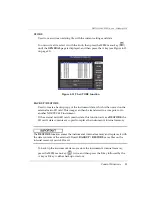
Enables automatic screen erase. You can set the display on an impedance plane 
(not sweep) so that the signal traces on the screen will be erased after a 

NOTE

NOTE

Summary of Contents for nortec 600

Page 1: ...s Manual This instruction manual contains essential information on how to use this Olympus product safely and effectively Before using this product thoroughly review this instruction manual Use the pr...

Page 2: ...tion contained therein and corresponds to the version of the product manufactured prior to the date appearing on the title page There could however be some differences between the manual and the produ...

Page 3: ...lity 8 Repair and Modification 9 Patent Rights Protection 9 Safety Symbols 10 Safety Signal Words 10 Note Signal Words 11 Safety 11 Warnings 12 Battery Precautions 13 Equipment Disposal 14 CE European...

Page 4: ...rdware Features 45 1 6 3 1 Instrument Stand 45 1 6 3 2 O Ring Gasket and Membrane Seals 46 1 6 3 3 Display Protection 46 1 6 4 Environmental Ratings 46 2 Software User Interface 49 2 1 Starting Up the...

Page 5: ...Key 82 4 3 2 Filter Menu MAIN FILTER Key 84 4 3 3 Special Menu MAIN FILTER Key 85 4 3 4 Display Menu DISP Key 87 4 3 5 Alarm Menu ALARM Key 91 4 3 6 Memory Menu MEM Key 92 4 3 7 Memory Text Editor 96...

Page 6: ...aluating Nonconductive Coating Paint Thickness All NORTEC 600 Models 181 5 2 4 Evaluating Metal Thickness and Using Thickness Curve Theory All NORTEC 600 Models 185 5 3 Advanced Dual Frequency Applica...

Page 7: ...nstrument Software without NORTEC PC 305 6 5 Creating a PDF 307 6 6 Issuing Remote Commands to the NORTEC 600 from a PC 308 6 7 Remotely Controlling the NORTEC 600 from a PC 318 6 8 Managing Files on...

Page 8: ...DMTA 10040 01EN Rev E February 2018 Table of Contents viii...

Page 9: ...t friendly use period GB gigabyte I O input output ID identification ID internal diameter IP ingress protection LCD liquid crystal display LED light emitting diode Li ion lithium ion MIL military mil...

Page 10: ...A 10040 01EN Rev E February 2018 List of Abbreviations x SPC statistical process control USB universal serial bus VGA video graphics array WEEE waste electrical and electronic equipment WT wall thickn...

Page 11: ...labels and symbols are attached to the instrument at the locations shown in Figure i 1 on page 1 If any or all of the labels or symbols are missing or illegible please contact Olympus Figure i 1 Label...

Page 12: ...i 2 Location of the serial number Table 1 Content of the rating label Content This symbol indicates the location of the membrane vent The direct current symbol Efficiency of battery chargers specific...

Page 13: ...ome The MSIP code for the NORTEC 600 is the following MSIP REM OYN N600 The CE marking is a declaration that this product conforms to all the applicable directives of the European Community See the De...

Page 14: ...month For example the 130050609 serial number indicates that the fifth unit 005 was produced on 6 September 2013 Table 2 Content of the probe adaptor labels Content The direct current symbol The WEEE...

Page 15: ...s for which listed controlled substances will not leak or chemically deteriorate while in the product The EFUP for the NORTEC 600 probe cable has been determined to be 15 years Note The Environment Fr...

Page 16: ...DMTA 10040 01EN Rev E February 2018 Labels and Symbols 6...

Page 17: ...als Do not use the NORTEC 600 for any purpose other than its intended use It must never be used to inspect or examine human or animal body parts Instruction Manual This instruction manual contains ess...

Page 18: ...ional stand alone external battery charger Olympus P N EPXT EC X U8767043 where X denotes the power cord type see Table 12 on page 342 Charger adaptor Olympus P N EP MCA X where X denotes the power co...

Page 19: ...d here has not been tested and is NOT supported at the time of publication of this manual Repair and Modification The NORTEC 600 does not contain any user serviceable parts Opening the instrument migh...

Page 20: ...ge Safety Signal Words The following safety signal words might appear in the documentation of the instrument The DANGER signal word indicates an imminently hazardous situation It calls attention to a...

Page 21: ...RTANT signal word calls attention to a note that provides important information or information essential to the completion of a task The NOTE signal word calls attention to an operating procedure prac...

Page 22: ...stall substitute parts or perform any unauthorized modification to the instrument Service instructions when applicable are for trained service personnel To avoid the risk of electric shock do not perf...

Page 23: ...tional Maritime Organization IMO the US Department of Transportation USDOT Transport Canada TC and others Please contact the transporter and confirm current regulations before transportation of lithiu...

Page 24: ...ables over 25 m 82 ft in length are not CE compliant WEEE Directive This device complies with the requirements of directive 2014 30 EU concerning electromagnetic compatibility directive 2014 35 EU con...

Page 25: ...tronic information products EIP RoHS MII EIP The China RoHS mark indicates the product s Environment Friendly Use Period EFUP The EFUP is defined as the number of years for which listed controlled sub...

Page 26: ...with the limits for an industrial device in accordance with the specifications of the EMC directive FCC USA Compliance This device complies with Part 15 of the FCC Rules Operation is subject to the f...

Page 27: ...h conditions specified in the Olympus Scientific Solutions Americas Inc Terms and Conditions available at http www olympus ims com en terms The Olympus warranty only covers equipment that has been use...

Page 28: ...product without incurring the responsibility for modifying previously manufactured products Technical Support Olympus is firmly committed to providing the highest level of customer service and produc...

Page 29: ...rument which uses eddy currents to detect surface flaws in various types of metals see Figure i 3 on page 19 The information in this manual is organized to explain the technology safety details hardwa...

Page 30: ...DMTA 10040 01EN Rev E February 2018 Introduction 20...

Page 31: ...duction is achieved with a coil that carries a current and that is placed in proximity to the test material The alternating current in the coil generates a changing magnetic field that interacts with...

Page 32: ...ROM Olympus P N N600 CD U8030151 Instrument transport case P N 600 TC U8780294 Universal PowerLink eddy current probe cable Olympus P N 9122083 U8800073 Although in some countries this item may be in...

Page 33: ...re 1 2 on page 24 illustrates the connections of the NORTEC 600 instrument with the charger adaptor the microSD card and a PC Charger adaptor AC power cord and probe cable Getting Started leaflet and...

Page 34: ...n unauthorized power cord may result in damage to instruments or serious injury to the user The DC power PROBE and BNC connectors are located on the top end of the NORTEC 600 see Figure 1 3 on page 24...

Page 35: ...ovable microSD memory card slot are located on the right hand side of the instrument hidden behind the input output I O door see Figure 1 4 on page 25 Figure 1 4 The connectors behind the input output...

Page 36: ...methods Directly from the NORTEC 600 charger adaptor Internal lithium ion battery Internal alkaline battery holder Press the power button to turn on the NORTEC 600 see Figure 1 6 on page 27 Pressing t...

Page 37: ...thium ion rechargeable battery when it is installed in the instrument A charger adaptor indicator light on the front panel of the unit displays the current status of the charger adaptor see Figure 1 6...

Page 38: ...so might cause an explosion or injury Do not attempt to power or charge other electronic equipment with the charger adaptor P N EP MCA X unless specifically instructed in the manual Misuse of the cha...

Page 39: ...power cable Table 3 on page 29 explains the indicators for the power status of the charger adaptor and the battery charge condition which are visible at the top of the front panel and in the user inte...

Page 40: ...l hole in the bottom center area that is covered on the inside by an environmentally sealed membrane vent This vent is a safety feature that is required in the event that the instrument battery fails...

Page 41: ...ered by the lithium ion battery and recharged via the charger adaptor both are supplied with the NORTEC 600 When properly maintained and when the instrument is operated under typical inspection condit...

Page 42: ...batteries for situations where an AC power source is not available and the internal Li ion battery is discharged When operated under typical inspection conditions the alkaline batteries typically pro...

Page 43: ...the instrument the battery indicator in the user interface displays ALK The charger adaptor does not recharge the batteries installed in the alkaline battery holder 1 5 Optional microSD Card Installa...

Page 44: ...clicks To remove the microSD card gently push the card into the instrument and release A spring loaded mechanism will partially eject the card and then you can grasp the card and remove it from the in...

Page 45: ...1 14 on page 35 and Figure 1 15 on page 36 show the main components on the NORTEC 600 instrument Figure 1 14 Overview of the NORTEC 600 hardware Front view Protective rubber bumpers D rings to attach...

Page 46: ...nt parameters within a menu In this manual the term knob is also used to refer to the SmartKnob The NORTEC 600 front panel features direct function keys that are used in combination with the SmartKnob...

Page 47: ...38 to Figure 1 20 on page 39 and Table 4 on page 40 The text labels on some keys may be replaced by pictograms depending on the keypad configuration In this document keys are referred to using the En...

Page 48: ...DMTA 10040 01EN Rev E February 2018 Chapter 1 38 Figure 1 17 The NORTEC 600 English keypad Figure 1 18 The NORTEC 600 Chinese keypad...

Page 49: ...DMTA 10040 01EN Rev E February 2018 Instrument Overview 39 Figure 1 19 The NORTEC 600 Japanese keypad Figure 1 20 The NORTEC 600 international keypad...

Page 50: ...vertical gain settings horizontal gain only or vertical gain only ERASE Direct function key used to erase the currently displayed image ANGLE Direct function key used to display the angle FREEZE Dire...

Page 51: ...hich controls functions such as previewing stored memory files recalling and editing stored files capture mode capture time and user information ADV SETUP Provides access to the instrument s advanced...

Page 52: ...side The two connectors are easily accessible from the front of the instrument see Figure 1 21 on page 42 Figure 1 21 Location of the PROBE LEMO and BNC connectors Do not allow metallic or foreign ob...

Page 53: ...essary to connect an external control for integrating the NORTEC 600 into a system For PC communication details see microSD and USB Port on page 44 Do not expose the instrument to harsh and wet enviro...

Page 54: ...all onboard data storage In the event the instrument is damaged beyond repair this microSD card can be removed at an authorized service center allowing you to recover critical data from the damaged i...

Page 55: ...C 600 instrument s physical features make it suitable for a variety of operating environments 1 6 3 1 Instrument Stand The NORTEC 600 features an articulating stand for variable viewing angles see Fig...

Page 56: ...600 DP U8780297 The display window is permanently bonded to the instrument case to fully seal the instrument If the display window becomes damaged the front part of the case must be replaced along wit...

Page 57: ...level of ingress protection performance once the instrument seals have been manipulated You must use sound judgment and take proper precautions before exposing the instrument to harsh environments The...

Page 58: ...DMTA 10040 01EN Rev E February 2018 Chapter 1 48...

Page 59: ...Up the Instrument When power is turned on the NORTEC 600 starts up in one of two modes depending on what is connected to the instrument If no probe is connected or if a probe that is not a PowerLink...

Page 60: ...be intuitive and the settings for each application will permit immediate inspection little or no additional instrument setup is needed To navigate the application menu 1 Rotate the knob to highlight...

Page 61: ...EEP LAST SETTINGS function to load the previous parameters if they are compatible with the probe or accessory that is detected This automatically sets up the instrument OR Bypass the stored program in...

Page 62: ...date also remain visible except when in full screen mode The rectangular readout in the top left corner of the screen is called the quick access bar see Figure 2 5 on page 53 It displays either the in...

Page 63: ...the main screen The displayed settings information can change depending on the menu key that is pressed The menu keys are the five keys located at the bottom of the front panel MAIN FILTER DISP ALARM...

Page 64: ...SP ALARM MEM or ADV SETUP Pressing the same menu key again will cycle through the available options and update the available functions which can then be adjusted 2 Select the function to be changed by...

Page 65: ...e ADV SETUP menu key To use the ALL SETTINGS menu 1 Press the ADV SETUP menu key 2 Press the B key 3 Press the FULL NEXT key to select the parameter to be adjusted 4 Rotate the knob to select the desi...

Page 66: ...structions in Using the ALL SETTINGS Menu on page 55 If the NORTEC 600 instrument is being used in noisy conditions an external horn can be used The horn connects to the I O connector on the back of t...

Page 67: ...orizontal voltage peak to peak VMAX Maximum vertical voltage from extended null line HMAX Maximum horizontal voltage from extended null line DEG PP Angle of VMAX peak to peak Figure 2 7 Example of VPP...

Page 68: ...DMTA 10040 01EN Rev E February 2018 Chapter 2 58 Figure 2 9 Example of VPP Figure 2 10 Example of HMAX Volts P P Vert Volts Max Horz or...

Page 69: ...DV SETUP menu key 2 Press the B key 3 Press the E key 4 Press the B key 5 Press the FULL NEXT key to navigate to the desired type and or location Only TOP LEFT and TOP RIGHT are valid locations for th...

Page 70: ...P RIGHT BOT LEFT bottom left BOT CNTR bottom center or BOT RGHT bottom right The performance and results of the real time readings are greatly affected by the D ERASE display erase and PERSIST persist...

Page 71: ...DMTA 10040 01EN Rev E February 2018 Software User Interface 61 Press the Return key to exit...

Page 72: ...DMTA 10040 01EN Rev E February 2018 Chapter 2 62...

Page 73: ...the user interface in the following languages English French Spanish German Japanese Chinese Russian Swedish Italian Portuguese Norwegian Hungarian Polish Dutch and Czech You can also change the char...

Page 74: ...can set the date and the time and select their respective format The NORTEC 600 saves all inspection results with their acquisition date To set the clock 1 Press the ADV SETUP menu key twice and then...

Page 75: ...on the external microSD card 3 4 Changing the Display Settings You can change the appearance of some display elements such as brightness auto erase VGA output and whether or not the application window...

Page 76: ...n 3 5 Changing the Display Brightness You can adjust the NORTEC 600 display brightness by changing the backlight intensity The display brightness can be set at 0 25 50 75 and 100 Choosing a high perce...

Page 77: ...ress the B key to enter the SYSTEM SETUP screen 2 Repeatedly press the FULL NEXT key until AUTO ERASE is highlighted 3 Use the knob to disable the function select OFF or enable the function select ON...

Page 78: ...b If the knobless entry function is enabled the frequency angle and the combined horizontal and vertical gain settings can be increased or decreased using keypad entries instead of the knob The knoble...

Page 79: ...nd rotating scanners when they are connected to the instrument The instrument is then configured according to the parameters programmed into the PowerLink ID chip Each PowerLink probe is programmed at...

Page 80: ...ent with a connected PowerLink probe or rotating scanner press the A key to use the PowerLink feature or press to proceed without using the PowerLink feature The KEEP LAST SETTINGS function lets you l...

Page 81: ...he lock button When activated the lock disables most of the instrument function keys menu keys and the knob This prevents inadvertent key entries after the instrument is calibrated and ready to procee...

Page 82: ...s in contact with the reference standard 1 Press and hold the A LIFT NULL direct function key until a beep sound signal is heard approximately 3 seconds and the text LIFT PROBE is displayed on the ins...

Page 83: ...DMTA 10040 01EN Rev E February 2018 Control Functions 73 Figure 4 3 Probe liftoff initially not horizontal Figure 4 4 The LIFT PROBE message after holding the A LIFT NULL key...

Page 84: ...EEZE key is to freeze the current image on the instrument screen for further evaluation When the FREEZE key is pressed the data acquisition stops and an indicator capital letter F is displayed on the...

Page 85: ...orizontally or combined vertically and horizontally see GAIN on page 76 for more details on changing the gain Pressing the ANGLE key after FREEZE is enabled will alter the screen image to estimate the...

Page 86: ...age 53 Pressing the ANGLE key will display the instrument s angle settings in the quick access bar shown in Figure 2 5 on page 53 The knob is the primary method of changing this setting For more infor...

Page 87: ...ee Menus on page 82 The following menu keys are available MAIN FILTER Provides access to the main menu which controls functions such as frequency gain angle and filters DISP Provides access to the dis...

Page 88: ...en capture image file to the removable external microSD card by holding the MAIN FILTER menu key and then pressing and holding the REF SAVE key until you hear a beep after which you release the keys A...

Page 89: ...rough the various gain control options in the following order H V GAIN combined horizontal and vertical gain H GAIN horizontal gain followed by V GAIN vertical gain Subsequent presses of the C key wil...

Page 90: ...until AMBIDEXTROUS is selected 3 Rotate the knob to select ON and then press the MAIN FILTER menu key to display the controls on the right side of the instrument see Figure 4 9 on page 80 Figure 4 9...

Page 91: ...full use of the NORTEC 600 display for inspections see Figure 4 10 on page 81 The instrument s settings can be displayed again by pressing the FULL NEXT key or any other function or menu key Figure 4...

Page 92: ...he A key With FREQ highlighted rotate the knob until the desired frequency is displayed To speed up the frequency selection process press the Enter key once while the FREQ function is highlighted to e...

Page 93: ...rimary method of adjusting gain is by turning the knob However gain may also be adjusted by using the knobless function for more details see Knobless Entry on page 78 To adjust the horizontal and vert...

Page 94: ...band To adjust the LO PASS filter settings press the MAIN FILTER menu key two times followed by the B key and then rotate the knob to the desired value CONT NUL continuous null CONT NUL allows a very...

Page 95: ...normally sufficient for most eddy current testing However HIGH probe drive is desirable in the following cases a If gain is insufficient at the lower probe drive settings b During testing of lower co...

Page 96: ...heat exchanger tubing applications see Heat Exchanger Tubing Applications on page 228 Slide Rule The NORTEC 600 instrument includes a useful slide rule tool for determining the standard depth of penet...

Page 97: ...adjust the display mode press the DISP menu key followed by the A key With DSP MODE highlighted rotate the knob until the desired display mode is displayed IMP Impedance mode is the most common displa...

Page 98: ...ly functional during dual frequency inspection For more details see Display Menu in Dual Frequency DISP Key on page 116 POSITION Used to select the NORTEC 600 instrument s null position By default the...

Page 99: ...D key and then rotate the knob to the desired setting V POS Changes the null position in the vertical axis To change the vertical position press the DISP menu key followed by the E key and then rotat...

Page 100: ...D ERASE or sweep mode SWEEP is activated In some applications PERSIST may slow down the instrument s data acquisition rate resulting in decreased instrument performance If this is the case it is reco...

Page 101: ...screen is magnified by applying a horizontal and vertical digital gain of 10 In ZOOM mode all display functions are disabled with the exception of ZOOM OFF or ON To enable ZOOM press the DISP menu key...

Page 102: ...el of the instrument or alternatively by using the NORTEC PC software included with each instrument Whenever a program stored data file is recalled the currently active instrument settings are overwri...

Page 103: ...ts the instrument and loads the instrument settings associated with the data file that is recalled To recall a stored data file press the MEM menu key rotate the knob until the desired data file is hi...

Page 104: ...ference image press the MEM menu key rotate the knob until the desired data file is highlighted and then press the D key Alternatively a reference image may be created using the current screen image b...

Page 105: ...ard This image can then be transferred to a computer or to another NORTEC 600 instrument If the external microSD card contains data this function acts as a RESTORE the SD card s data contents are copi...

Page 106: ...ELAYED It is possible to specify a delay CAPTURE DELAY for data saving after the REF SAVE key is pressed This feature can help you correctly place the probe before data is saved for example during sca...

Page 107: ...FULL NEXT key to accept the characters 5 After the FILE NAME or FILE NOTE has been edited press to save the changes or press to exit without saving By default the text editor highlights the entire or...

Page 108: ...ULL NEXT key until the cursor is in the correct location 3 Use the knob to select characters and press the FULL NEXT key to accept characters 4 After all the desired characters have been selected pres...

Page 109: ...about SYSTEM SETUP see Setting the User Interface Language and the Decimal Symbol on page 63 APPL SELECT application select Provides access to the application selection menu which opens in a new wind...

Page 110: ...used eddy current inspections The NORTEC 600 applications are designed for quick setup of the instrument However always follow published maintenance procedures when inspecting ALL SETTINGS The ALL SE...

Page 111: ...e NORTEC 600 instrument does not use an enter key to save the selection made on any of its menus Instead the selected displayed value is automatically saved FRQ MODE frequency mode This option which s...

Page 112: ...equency mode 1 Press the ADV SETUP menu key 2 Press the C key and then rotate the knob to select the desired value DUAL for dual frequency or SINGLE for single frequency Dual frequency controls Dual f...

Page 113: ...details see MIX Menu in Dual Frequency MAIN FILTER Key on page 113 COLOR The NORTEC 600 instrument includes user selectable color schemes The color palate on the screen can be changed as follows 1 Pr...

Page 114: ...editor 3 Rotate the knob to select the characters of the password When finished press the A key to ACCEPT 4 Press the FULL NEXT key to navigate to another item to protect with a password and repeat st...

Page 115: ...sentative Contact information for your region can be found by visiting the Olympus website at http www olympus ims com en contact us ABOUT This feature displays the instrument configuration and other...

Page 116: ...access the BATT TEMP menu press the ADV SETUP menu key followed by the D key and then the A key To exit press the Return key LEGAL INFO Displays legal or patent rights protection information for the...

Page 117: ...d LED TEST To access the TESTS menu press the ADV SETUP menu key followed by the D key Rotate the knob until the desired test is shown and then press the A key to begin the test To exit the TESTS menu...

Page 118: ...each individual LED should display a sequence of green yellow orange and red colors before continuing to the next individual LED color sequence If any of these colors are not present the LED is not wo...

Page 119: ...n page 77 4 4 1 Frequency FREQ 1 Menu MAIN FILTER Key FREQ 1 frequency 1 The FREQ 1 setting determines the frequency 1 drive signal of the eddy current probe This is adjustable from 10 Hz 0 01 kHz to...

Page 120: ...gle setting press the MAIN FILTER menu key followed by the B key Once the ANGLE function is highlighted rotate the knob until the desired angle is displayed To be able to adjust the angle more precise...

Page 121: ...he knob will then adjust only the vertical gain To speed up the gain selection process while the combined horizontal and vertical gain horizontal gain or vertical gain function is highlighted press on...

Page 122: ...the ANGLE function is highlighted to enable the fine knob function ANGLE will be underlined when this function is enabled The angle can then be changed in 0 1 degree increments To turn off the fine k...

Page 123: ...derlined when this function is enabled The gain can then be changed in 1 0 dB increments To turn off the coarse knob function press one more time which returns to gain adjustments in 0 1 dB increments...

Page 124: ...be turned on which is useful to keep the null point of the eddy current probe at the specified point if required When turned on this function adds a 0 2 Hz 0 5 Hz or 1 Hz high pass filter By default t...

Page 125: ...ey four times followed by the B key With PRB CONN highlighted rotate the knob to select the desired connector LEMO 16 or BNC SIG TYPE SIG TYPE signal type absolute or differential is displayed only wh...

Page 126: ...gnal is shown moving horizontally and vertically ALL IN 1 ALL IN 1 mode is used to display the signal traces associated with both FREQ 1 FREQ 2 and the MIX signal at the same time each with a differen...

Page 127: ...With SWP MODE highlighted rotate the knob to select the desired signal AUTO Y or AUTO XY V POS vertical position Vertical position is used to control the signal trace shown on the instrument screen an...

Page 128: ...disabled the screen is only erased if the ERASE direct function key is pressed To choose when the sweep signal is erased press the DISP menu key twice followed by the E key With SWP ERS highlighted r...

Page 129: ...cedures are also a good starting point if you need to write any inspection procedures based on the NORTEC 600 The application examples presented here are not intended to replace any original equipment...

Page 130: ...tion materials are shown in Figure 5 1 on page 120 Figure 5 1 Materials surface breaking cracks The following products are used in this procedure Right angle flexible metal shaft surface probe 12 7 cm...

Page 131: ...nu key once followed by the A key APPL SELECT to open the application selection menu Select Surface Cracks with the knob SmartKnob and then press to accept see Figure 5 2 on page 121 Figure 5 2 The Su...

Page 132: ...nd hold the A LIFT NULL key on the NORTEC 600 to activate the automatic lift off function After a brief moment the NORTEC 600 beeps and displays LIFT PROBE at the top of the screen When this text is d...

Page 133: ...complete the calibration 6 Press the ANGLE key The ANGLE parameter defaults to the coarse mode Press the Enter key in order to switch the ANGLE parameter to the fine mode Adjust the ANGLE value with t...

Page 134: ...rom the crosshairs see Figure 5 5 on page 124 Figure 5 5 Adjusting the horizontal gain 8 Press the GAIN key to display V GAIN in the upper left corner of the screen and then increase the vertical gain...

Page 135: ...Alarm Menus on page 292 2 Depending on your requirements set the display erase or persistence values to automatically refresh the screen For more details about screen erase options see D ERASE displa...

Page 136: ...NORTEC 600D Models This procedure is intended for the general purpose inspection of aircraft fastener holes in aluminum material and has been prepared for a 12 70 mm 0 50 in diameter hole At the end o...

Page 137: ...lection differential coil configuration P N SUB 28 32 U8600488 Eddy current hole standard for demonstration purposes not certified P N RSTD 10135 U8863213 To set the initial NORTEC 600 configuration 1...

Page 138: ...le and then press the A LIFT NULL key Note that the scanner should be stopped when nulling the instrument 2 Hold the probe in the hole and properly aligned on the long crack If this is your first scan...

Page 139: ...et the signal angle according to one of the following two alternative methods Before proceeding check which method is better suited to your needs First alternative While holding the probe still rotati...

Page 140: ...rface of the sample with the head of the probe and adjust the signal angle so that the tip of the signal extends to the right of the impedance plane see Figure 5 14 on page 130 Figure 5 14 Adjusting t...

Page 141: ...nal reaches the top of the screen which is 100 screen height see Figure 5 16 on page 131 Figure 5 16 Adjusting the vertical gain At this point the configuration is nearly finished 6 If required fine t...

Page 142: ...see Alarm Menus on page 292 2 Check if any other display modes such as the IMP and the WATERFALL display modes might be useful for your purposes For more details about screen options see Display Menu...

Page 143: ...ible differences when using a ferromagnetic material as compared to aluminum A different lift off probe motion angle in the good hole A different notch angle in relation to the lift off closer to 90 L...

Page 144: ...or Figure 8 Signals The most recent digital filtering technology used on the NORTEC 600 includes improvements to the filter system The NORTEC 600 features a new parameter named FILT TYP filter type w...

Page 145: ...tating probes or in special engine inspection applications The Figure 8 filter is also the default filter type for nonrotating applications such as surface inspection Figure 5 21 on page 135 shows the...

Page 146: ...O 6687 cable connects reflection coil configuration probes with triaxial Fischer LEMO connector to NORTEC 500 600 1000 and 2000 Series instrument 16 pin LEMO 1 83 m 6 ft length P N SPO 6687 U8800538 S...

Page 147: ...ayed lift the probe vertically try to avoid tilting and wait for the message to disappear 3 Repeat step 2 until you become familiar with the automatic lift off function It may take some practice to ob...

Page 148: ...that it is as close to horizontal as possible see Figure 5 25 on page 138 Figure 5 25 The lower lift off signal as close as possible to horizontal 7 Press the GAIN key three times to access the V GAIN...

Page 149: ...FULL NEXT key to toggle to full screen mode see Figure 5 27 on page 139 To test the calibration place the probe successively on the cracked and uncracked fasteners and ensure that the cracked fastener...

Page 150: ...ersistence values to automatically refresh the screen For more details about screen erase options see D ERASE display erase on page 89 and PERSIST variable persistence on page 89 The list of all param...

Page 151: ...terials All NORTEC 600 Models The procedure in this section is the easiest and most efficient way to perform a general purpose weld inspection on ferromagnetic material such as carbon steel using the...

Page 152: ...mm 0 02 in 0 04 in and 0 08 in block overall dimensions 25 4 mm 101 6 mm 6 4 mm 1 in 4 in 0 25 in with four 0 5 mm 0 0197 in nonconductive shims to simulate paint thickness P N SRSM 51020S WLD U886057...

Page 153: ...obe tip see Figure 5 32 on page 143 perpendicularly to the notches and then press the A LIFT NULL key Figure 5 32 The longest face of the probe tip 2 With the longest face of the probe tip oriented pe...

Page 154: ...igure 5 34 The notch signal oriented vertically 5 Press the GAIN key once and adjust the H V GAIN until the notch signal reaches about 90 of the screen height see Figure 5 35 on page 144 Figure 5 35 A...

Page 155: ...ay erase or persistence values to automatically refresh the screen For more details about screen erase options see D ERASE display erase on page 89 and PERSIST variable persistence on page 89 You can...

Page 156: ...actual part recommended procedure 1 Check the paint thickness on the part you are inspecting and calibrate the weld probe using the proper shim thickness that corresponds with the measured paint thic...

Page 157: ...ractice your weld inspection for example by using an optional weld sample such as Olympus P N WLD SAMPLE U8860581 The list of all parameters is shown in Figure 5 39 on page 148 Key for images at left...

Page 158: ...geometry Figure 5 39 The list of all parameters 5 1 5 Evaluating Paint Thickness on Ferromagnetic Material All NORTEC 600 Models This section presents an improved version of a widely used well known...

Page 159: ...e standard with certifications steel with EDM notch depths of 0 5 mm 1 0 mm and 2 0 mm 0 02 in 0 04 in and 0 08 in block overall dimensions 25 4 mm 101 6 mm 6 4 mm 1 in 4 in 0 25 in with four 0 5 mm 0...

Page 160: ...20 using the knob To calibrate the signals 1 Place the probe on the standard between two notches without any shim and then press and hold the A LIFT NULL key to activate the automatic lift off functio...

Page 161: ...dot reaches the limit on the left side of the 10 10 grid 0 horizontal see Figure 5 42 on page 151 Figure 5 42 Decreasing the GAIN to adjust the signal 4 While firmly pressing the probe on the 2 0 mm...

Page 162: ...s for different thicknesses 6 Press and hold the REF SAVE key to set the current signal as the reference signal 7 Set the V POS E key to 50 and then press the ERASE key The paint thickness setup is no...

Page 163: ...shown in Figure 5 46 on page 153 The default setting for the reading type RDG1 TYP is VMAX which uses the vertical maximum amplitude For this procedure however it is recommended to select HMAX which...

Page 164: ...ivity probe 16 pin LEMO 60 kHz or 480 kHz when it is connected to the instrument With this probe type the instrument reconfigures the operating parameters to permit conductivity measurements In this o...

Page 165: ...0 To set the initial NORTEC 600 configuration 1 Connect the conductivity probe cable to the NORTEC 600 instrument s PROBE connector to access the conductivity function see Figure 5 48 on page 155 Figu...

Page 166: ...robe on the lowest IACS percentage standard without a shim Set the conductivity value for calibration point 1 COND1 by rotating the knob to the value of the certified standard and then selecting STORE...

Page 167: ...5 51 on page 157 4 Place the probe on the highest IACS percentage standard with the 4 mil shim and then select STORE4 E key Figure 5 51 The displayed instruction 4 5 Complete the calibration by selec...

Page 168: ...he conductivity probe the conductivity and coating thickness readings on the screen are refreshed renewed Conductivity mode with impedance plane While in conductivity coating thickness mode the NORTEC...

Page 169: ...ty is outside the low or high value 5 Press the E key to enable the audible alarm HORN and then rotate the knob to the OFF LOW or HIGH setting To set the coating thickness alarm 1 Press the ALARM menu...

Page 170: ...following products are used in this procedure Special purpose aircraft wheel inspection probe P N WP 3 1537 L Cable 1 83 m 6 ft length bridge coil configuration 16 pin LEMO to Fischer LEMO triaxial SP...

Page 171: ...cation To calibrate the signals 1 Press the MAIN FILTER menu key and set the FREQ A key to 200 kHz using the knob 2 Place the probe at the approximate midpoint on the standard between two notches and...

Page 172: ...dth press the ERASE key 5 Scan the center notch only and then press the FREEZE key see Figure 5 56 on page 162 Figure 5 56 Scanning the center notch 6 Press the ANGLE key and then adjust the signal an...

Page 173: ...ey while adjusting the ANGLE Figure 5 57 Setting the signal as close as possible to horizontal 7 Press the GAIN key 3 times to access the V GAIN parameter and then increase the vertical gain with the...

Page 174: ...he example shown in Figure 5 59 on page 164 If necessary freeze the signal again and fine tune the vertical gain or angle Figure 5 59 The results after scanning the standard To fine tune the instrumen...

Page 175: ...SIST variable persistence on page 89 3 Press the FULL NEXT key to toggle to the full screen mode and then scan the standard The resulting signal should resemble the example shown in Figure 5 61 on pag...

Page 176: ...anslation Indexing Scanner NORTEC 600S and NORTEC 600D Models This section contains a procedure for inspecting critical fastener holes using Olympus indexing rotating scanner model PS5 AL The NORTEC 6...

Page 177: ...nnect the scanner cable to both the rotating scanner and the PROBE connector on the NORTEC 600 2 When prompted select CONTINUE A key to accept the PowerLink information 3 Press the ADV SETUP menu key...

Page 178: ...and then press the MAIN FILTER menu key twice and set the SCAN RPM E key to 240 5 Press the MAIN FILTER menu key and then change the FILT TYP C key to FIG 6 see Figure 5 64 on page 168 This procedure...

Page 179: ...it is as horizontal as possible and the notch signal points upward see Figure 5 65 on page 169 Figure 5 65 Adjusting the signal angle 7 Press the GAIN key and then decrease the horizontal gain until t...

Page 180: ...ght 100 vertical see Figure 5 67 on page 170 Figure 5 67 Adjusting the vertical gain 9 Press the DISP menu key and then set the SYNC ANG D key to center the notch signal on the strip chart see Figure...

Page 181: ...e motor switch and scan the entire hole Closely observe the waterfall display and if necessary increase the W END value D key if the waterfall display has been cut off erased or refreshed before the s...

Page 182: ...erfall cursor 16 Press the FULL NEXT key to toggle to the full screen mode and then scan the standard The scan result should resemble the example image shown in Figure 5 70 on page 172 The list of all...

Page 183: ...lder eddy current procedures that are still used in eddy current training classes These training procedures are useful in explaining the effect that various parameters have on eddy currents parameters...

Page 184: ...9213552 SR 500Hz 60KHZ 44 U8623007 SPO 6687 cable for reflection coil configuration probes with triaxial Fischer LEMO connector to NORTEC 500 600 1000 or 2000 series instrument 16 pin LEMO 1 83 m 6 f...

Page 185: ...Press the DISP menu key and set the POSITION C key to TOP CNTR 4 Press the DISP menu key again and set the GRID D key to OFF 5 Press the ALARM menu key and set the ALARM 1 A key to OFF 6 Press the MAI...

Page 186: ...ection of the standard used for impedance plane theory Figure 5 75 Adjusting the signal angle to 90 10 Place the probe on the 45 conductivity sample and then press the GAIN key and decrease the gain u...

Page 187: ...ivity and magnetic permeability on the impedance plane see Figure 5 77 on page 177 Figure 5 77 Displaying the effect of conductivity and magnetic permeability 5 2 2 Sorting Metals by Evaluating Conduc...

Page 188: ...gure 5 78 The Surface Cracks application 3 Press the DISP menu key and set the POSITION C key to BOT RGHT 4 Press the MAIN FILTER menu key and set the FREQ A key to 60 kHz 5 Set the GAIN C key to appr...

Page 189: ...e proper timing with the automatic lift off function but once mastered this function will help you obtain a faster calibration 8 Place the probe successively on the 17 32 and 45 conductivity samples a...

Page 190: ...parameter and increase the vertical gain until the upper signal reaches 90 of the screen height see Figure 5 82 on page 180 Figure 5 82 Adjusting the vertical gain 11 Press the ALARM menu key twice a...

Page 191: ...for acceptance or rejection and the horizontal position represents the lift off Figure 5 83 Using the vertical position of the signal to accept or reject the sample 5 2 3 Evaluating Nonconductive Coat...

Page 192: ...ey to 60 kHz 5 Set the GAIN C key to approximately 50 dB 6 Turn the standard upside down to expose the larger face see Figure 5 85 on page 182 place the probe on an area that is free of defects and th...

Page 193: ...he lift off angle to 90 8 Press the ERASE key place the probe on the sample again this time use a larger lift off or paint thickness value for example the thickness of three business cards and then pr...

Page 194: ...e H POS D key to 0 then up to 100 and back down to 50 A horizontal mark is created see Figure 5 88 on page 184 Figure 5 88 Using H POS to create a horizontal mark 10 Repeat step 9 using two business c...

Page 195: ...Using the vertical signal deflection to evaluate unknown thicknesses 5 2 4 Evaluating Metal Thickness and Using Thickness Curve Theory All NORTEC 600 Models This section outlines the typical thickness...

Page 196: ...encies such as 500 Hz 1 kHz 3 kHz and 5 kHz 5 Place the probe on the thickest part of the standard s tapered area see Figure 5 92 on page 186 and then press and hold the A LIFT NULL key to activate th...

Page 197: ...off function but once mastered this function will help you obtain a faster calibration 7 Press the ERASE key then slowly scan the tapered area and then after completing the scan press the FREEZE key A...

Page 198: ...crease the gain until the signal extends across most of the screen see Figure 5 96 on page 189 Figure 5 95 Adjusting the gain 10 Press the FREEZE key to unfreeze the acquisition and then press the FUL...

Page 199: ...the tapered part 5 3 Advanced Dual Frequency Applications This section contains several procedures that provide advanced details on the dual frequency function of the NORTEC 600 All procedures in this...

Page 200: ...ual frequency for corrosion The following products are used in this procedure Surface probe a standard reflection detachable surface probe with a diameter of 11 2 mm 0 44 in and an operating range of...

Page 201: ...Dual Frequency Sub Surface application 3 Press the DISP menu key twice and then set the POSITION C key to TOP LEFT using the knob 4 Press the DISP menu key again and then set the POS 2 C key to TOP L...

Page 202: ...e 5 99 The list of dual frequency parameters To calibrate the signals 1 Press the MAIN FILTER menu key once and then set the FREQ A key value to 3 0 kHz using the knob 2 Press the MAIN FILTER menu key...

Page 203: ...of the screen the green signal in Figure 5 101 on page 193 If necessary you can press the ERASE key to clear screen which may make it easier to adjust the ANGLE value Figure 5 101 Adjusting the angle...

Page 204: ...y 2 lift off signal 6 Place the probe on position 1 and then press the A LIFT NULL key 7 Place the probe on position 2 see Figure 5 103 on page 194 and then press the FREEZE key Figure 5 103 Position...

Page 205: ...il the frequency 1 signal at position 2 is at 20 of the screen height see Figure 5 105 on page 195 Figure 5 105 Adjusting the gain for frequency 1 9 Press the GAIN key three more times and then increa...

Page 206: ...d set the POSITION C key to BOT RGHT 12 Place the probe again on position 1 and then press the A LIFT NULL key 13 Lift the probe into the air press the MAIN FILTER menu key and then while gently tappi...

Page 207: ...s the A LIFT NULL key 15 While firmly pressing the probe at position 2 on the standard observe the MIX signal point and then press the MAIN FILTER menu key and decrease the H GAIN 2 D key until the MI...

Page 208: ...channel and then decrease the H GAIN D key until the lift off signal from the MIX channel is oriented toward the left see Figure 5 109 on page 198 Figure 5 109 Adjusting the H GAIN value 18 Place the...

Page 209: ...signal s maximum amplitude reaches 80 of the screen height see Figure 5 111 on page 199 Figure 5 111 Adjusting the V MIX GN value 22 Press the FREEZE key to unfreeze the acquisition 23 Press the FULL...

Page 210: ...your requirements set the alarm parameters horn or external horn louder For more details about alarms see Alarm Menus on page 292 2 Depending on your requirements set the display erase or persistence...

Page 211: ...ncy in a Lap Splice with Anodized and Alodine Rivets NORTEC 600D Model The procedure in this section uses the dual frequency and mix channel functions to help reduce undesirable signal variations caus...

Page 212: ...600 1000 or 2000 series instrument 16 pin LEMO 1 83 m 6 ft length P N SPO 6687 U8800538 Special purpose anodized reference standard P N NDT1087 4 U8860779 and plastic guides for alodine reference sta...

Page 213: ...r on the NORTEC 600 2 Press the ADV SETUP menu key once and select APPL SELECT A key to open the application selection menu Select Dual Frequency Sub Surface with the knob then press to accept see Fig...

Page 214: ...then set the RDG2 TYP to OFF When done press the Return key The list of dual frequency parameters is shown in Figure 5 116 on page 204 Figure 5 116 The list of dual frequency parameters To calibrate t...

Page 215: ...he probe 5 While holding the probe in place press the ANGLE key and then adjust the ANGLE until the signal is as horizontal as possible 20 vertical see Figure 5 118 on page 205 Figure 5 118 Adjusting...

Page 216: ...obe press the FREEZE key The probe and business cards can now be put aside 8 Press the GAIN key and then adjust the amplitude of the frequency 1 signal so that it is exactly 6 divisions away from the...

Page 217: ...djusting the amplitude of the frequency 2 signal 10 Press the FREEZE key to unfreeze the acquisition 11 Place the probe on position 1 of the standard see Figure 5 117 on page 205 and then press the A...

Page 218: ...y 1 signal green until it extends exactly 5 divisions to the left of the null point see Figure 5 123 on page 208 Figure 5 123 Adjusting the horizontal amplitude of the frequency 1 signal 14 Press the...

Page 219: ...l amplitude of the frequency 2 signal red until it extends exactly 5 divisions to the left of the null point see Figure 5 125 on page 209 Figure 5 125 Adjusting the horizontal amplitude of the frequen...

Page 220: ...the DISP menu key and then set the DSP MODE A key to IMP the CHANNEL B key to MIX and the POSITION C key to BOT RGHT 19 Press the MAIN FILTER menu key three times and then set the MIX ANG E key to 18...

Page 221: ...st the V GAIN 2 E key until the mix signal extends upward from the null point 4 vertical divisions see Figure 5 128 on page 211 Figure 5 128 Adjusting the V GAIN 2 value 23 Press the MAIN FILTER menu...

Page 222: ...is contained within the first vertical division above the null point see Figure 5 129 on page 212 Figure 5 129 Adjusting the V GAIN value 26 If necessary press the ERASE key to check the mix signal s...

Page 223: ...key until the mix signal orange reaches the same vertical height as the null point see Figure 5 131 on page 213 Figure 5 131 Adjusting the ANGLE value 30 Press the MAIN FILTER menu key once 31 While f...

Page 224: ...key to 50 the LEFT D key to 10 and the RIGHT E key to 110 35 Press the FULL NEXT key to toggle to the full screen mode 36 Place the probe on position 1 and then perform a final scan of both fastener r...

Page 225: ...this procedure has been prepared using a differential bobbin probe other types of tube probe coils can also easily be used for example differential pancake coils for air conditioner tubing Several tip...

Page 226: ...qually as well with frequency 2 as the highest frequency Inspection materials are shown in Figure 5 135 on page 216 Figure 5 135 Materials dual frequency for heat exchanger tubing The following produc...

Page 227: ...e and the foot switch adaptor cable to the PROBE connector on the NORTEC 600 2 Press the ADV SETUP menu key once then select APPL SELECT A key to open the application selection menu Select Heat Exchan...

Page 228: ...sible on the NORTEC 600 screen press the FREEZE key See Figure 5 137 on page 218 Figure 5 137 The scan of the thru wall hole 3 Press the ANGLE key and then rotate the frequency 1 signal green until th...

Page 229: ...gnal reaches about 4 vertical divisions in height see Figure 5 139 on page 219 Figure 5 139 Adjusting the frequency 1 gain 5 Press the ANGLE key twice and then adjust the angle of the frequency 2 sign...

Page 230: ...in a defect free area near the tube s support ring and then press the NULL foot switch Scan the support ring and press the FREEZE key when done see Figure 5 141 on page 220 Figure 5 141 The scan of th...

Page 231: ...then adjust the H V GAIN 2 until the support ring s frequency 2 signal extends across approximately 10 horizontal divisions on the screen see Figure 5 144 on page 222 Figure 5 143 Adjusting the gain...

Page 232: ...rds 5 seconds of the support ring s signal and automatically performs signal mixing see Figure 5 144 on page 222 Figure 5 144 The support ring scan with AUTO MIX 14 If necessary repeat step 13 to prac...

Page 233: ...pulling motion see Figure 5 146 on page 223 Figure 5 146 The scan of the thru wall hole To fine tune the instrument settings 1 Improve the already functional configuration by fine tuning the settings...

Page 234: ...this value see Figure 5 147 on page 224 Figure 5 147 Fine tuning the MIX angle 2 Press the FULL NEXT key to activate the full screen mode and then scan the five flat bottom holes The signal should res...

Page 235: ...quency 2 as a strip chart sweep by pressing the DISP menu key three times and setting the FRQ2 DSP A key to AUTO Y see Figure 5 150 on page 226 If necessary adjust the SWP TIME C Key to display a long...

Page 236: ...enu key repeatedly until the DISPLAY page is shown and then setting the DSP MODE A key to IMP 3 Set the CHANNEL B key to MIX and then set the POSITION C key to CENTER 4 Press the DISP menu key again s...

Page 237: ...ies starting at half the prime frequency Note that absolute response is generally not recommended for small defects such as the flat bottom holes in the calibration standard tube To perform absolute m...

Page 238: ...se grid 5 4 Heat Exchanger Tubing Applications The NORTEC 600 can be used to inspect various types of heat exchanger tubing composed of different alloys Although small in size the instrument contains...

Page 239: ...00 series stainless steel Duplex stainless steel ECT or RFT TEO or TRX Higher frequency TRX dual exciter probes are recommended they are easier to use and procure Carbon steel finned tubing typically...

Page 240: ...T Pitting Wear and Cracks NORTEC 600D Model In this application an eddy current bobbin probe is used to identify localized small defects such as pitting wear and cracks in tubing made of nonferromagne...

Page 241: ...ects in the tube This application uses a probe adaptor that is configured for differential mode The differential configuration subtracts the signals obtained by both coils and as such is ideal for det...

Page 242: ...oil probes which are used to inspect copper finned tubes in air conditioner units Although not illustrated here cross axis coil probes are used in a similar way as A C probes but they typically requir...

Page 243: ...hanger tubing absolute differential 14 8 mm 0 583 in diameter 15 kHz center frequency 20 m 65 6 ft cable P N TEA 148 015 N05 U8282109 Differential and absolute eddy current probe adaptor P N CBAS 1081...

Page 244: ...quency 1 1 Place the probe in a defect free zone of the calibration standard near the small thru wall hole 1 3 mm 0 052 in and then press the NULL foot switch 2 Slowly scan the smallest thru wall hole...

Page 245: ...u wall hole 3 Press the ANGLE key and then rotate the frequency 1 signal green until the hole signal reaches a phase of about 40 see Figure 5 161 on page 236 Choose the polar WEB grid shown in this ex...

Page 246: ...ess the GAIN key and then increase the frequency 1 gain until the hole signal reaches about 6 vertical divisions in height see Figure 5 162 on page 236 If necessary adjust the ANGLE after you have inc...

Page 247: ...the support ring signal is visible on the NORTEC 600 screen press the FREEZE key 8 If the support ring signal exceeds 80 of full screen height press the GAIN key and lower the gain The support ring s...

Page 248: ...ULL foot switch 10 Scan the tube between the support ring and the 1 3 mm 0 052 in thru wall hole to verify the frequency 1 calibration see Figure 5 165 on page 238 For improved clarity the verified si...

Page 249: ...key twice to check the frequency 2 value When you use the MIX function the frequency 2 value must be at least one half of the frequency 1 value 3 Place the probe in a defect free area near the tube s...

Page 250: ...ressing the ERASE foot switch as required to clear the screen When the hole signal is visible on the NORTEC 600 screen press the FREEZE key see Figure 5 168 on page 240 Figure 5 168 The frequency 2 sc...

Page 251: ...gle adjustment for the 1 3 mm 0 052 in thru wall hole To record and cancel the support signal using AUTO MIX 1 Press the DISP menu key followed by CHANNEL B key and then rotate the knob until the MIX...

Page 252: ...m the support ring see Figure 5 170 on page 242 Figure 5 170 The support ring signal after AUTO MIX 6 Place the probe in a defect free zone of the calibration standard near the small thru wall hole 1...

Page 253: ...IX ANGLE E key and then rotate the MIX signal until the hole signal reaches a phase of approximately 40 see Figure 5 172 on page 243 The direct function keys on the left side of the instrument screen...

Page 254: ...tal and vertical gain adjustment is not available while using the MIX menu Adjustments to horizontal and vertical gain must be made separately and equally Figure 5 173 The thru wall hole signal after...

Page 255: ...lled and used later to show additional features To verify the setup with the support ring over a flaw For this subprocedure the support ring is moved directly over a flaw in order to verify that the f...

Page 256: ...gure 5 176 on page 246 and then press the NULL foot switch Figure 5 176 The null position after moving the support ring 3 Scan the tube for defects see Figure 5 177 on page 247 Slide the o rings and s...

Page 257: ...ect free area see Figure 5 176 on page 246 5 Press the DISP menu key followed by CHANNEL B key and then rotate the knob until FREQ 1 is displayed 6 Press the NULL foot switch and scan the tube It shou...

Page 258: ...in a defect free area near the tube s support ring and then press the NULL foot switch 4 Scan the tube 5 Press and hold the REF SAVE key until you hear a beep The REF SAVE key can be used in the foll...

Page 259: ...e used with frequency 2 to create a strip chart type of display that represents the tube inspection history This section s setup uses settings from the previous section Alternatively the saved file ca...

Page 260: ...b until 20 is displayed 4 Press FRQ2 DSP A key and rotate the knob until AUTO Y is displayed 5 Place the probe in a defect free area near the tube s support ring and then press the NULL foot switch 6...

Page 261: ...n Inspecting Heat Exchanger Tubing Using Dual Frequency NORTEC 600D Model on page 215 The following products are used in this procedure Eddy current bobbin probe for heat exchanger tubing absolute dif...

Page 262: ...n and Corrosion application To calibrate the signals 1 Press FREQ frequency A key and use the knob to select 5 kHz 2 Place the probe in a defect free area of the calibration standard near the 10 ID fl...

Page 263: ...e signal until the OD groove signal reaches a phase of approximately 10 see Figure 5 185 on page 253 Figure 5 185 Adjusting the signal phase 5 Press the GAIN key and then increase the gain until the h...

Page 264: ...t free area of the calibration standard near the 10 ID flaw and then press the NULL foot switch 7 Scan the 10 ID and 20 OD flaws 8 Press and hold the REF SAVE key until you hear a beep and then press...

Page 265: ...et as a reference image 9 Place the probe in a defect free area of the calibration standard near the 10 ID flaw and then press the NULL foot switch 10 Press the FULL NEXT key 11 Scan the entire length...

Page 266: ...tance is essential and critical for the pickup coils to be able to sense the remote magnetic field rather than the direct field The basic probe is made of one exciter coil and two pickup coils see Fig...

Page 267: ...inuity signal is subtracted diminished and therefore not useful To detect longer or gradual discontinuities absolute mode must be used Figure 5 190 An example of an RFT differential signal response Du...

Page 268: ...tance from the support at which a defect can be reliably detected With a typical single frequency configuration a corrosion pit can be detected from a distance equivalent to about one tube OD outside...

Page 269: ...21 0001 Q7670054 Demonstration calibration standard P N MESX0397 Q7800046 and large support for calibration standard P N MESX0400 Q7800049 Convenient highly recommended items however not mandatory foo...

Page 270: ...the probe in a defect free area of the calibration standard near the thru wall flaw and then press the NULL foot switch 3 Slowly scan the tube until the thru wall flaw is displayed and then press the...

Page 271: ...ress the GAIN key and then increase the gain until the hole signal reaches approximately 4 to 6 vertical divisions in height Press the FREEZE key to enable signal acquisition see Figure 5 196 on page...

Page 272: ...ne see Figure 5 197 on page 262 Remote field testing RFT requires a slow inspection speed and practice Scan the tube at several inspection speeds and note how the signal varies until you are comfortab...

Page 273: ...by FREQ 2 A key and then rotate the knob until 200 Hz or less is displayed 2 Press the DISP menu key followed by CHANNEL B key and then rotate the knob until FREQ 2 is displayed 3 Place the probe in...

Page 274: ...ess the ANGLE key and then rotate the signal until the thru wall signal is vertical on the instrument screen see Figure 5 200 on page 264 Figure 5 200 Angle adjustment in FREQ 2 6 Adjust the support r...

Page 275: ...on 8 Place the probe in a defect free area of the calibration standard near the thru wall flaw and then press the NULL foot switch 9 Scan the entire length of the tube and verify that the thru wall fl...

Page 276: ...when done 4 Press the MAIN FILTER menu key three times The MIX menu appears see Figure 5 203 on page 266 Figure 5 203 The MIX menu 5 Press MIX ANG mix angle E key and if necessary adjust the thru wal...

Page 277: ...dication of the support ring should be minimized as shown in Figure 5 204 on page 267 Figure 5 204 The scan of entire tube length after AUTO MIX 9 Press the FREEZE key followed by MIX ANG mix angle E...

Page 278: ...o horizontal and vertical gain must be made separately and equally 11 Press the FREEZE key to enable signal acquisition 12 Place the probe in a defect free area near the thru wall flaw and then press...

Page 279: ...Hz LO PASS filter left with scan rate too fast right 5 4 3 3 Using the ALL IN 1 Display This section shows you how to use ALL IN 1 to display the small cluster of four corrosion pits under the suppor...

Page 280: ...gure 5 207 on page 270 a Frequency 1 signal center screen b MIX signal center right screen c Frequency 2 as a strip chart bottom screen Figure 5 207 ALL IN 1 display of cluster of 4 corrosion pits und...

Page 281: ...on page 271 Figure 5 209 An example of an RFT absolute signal response The use of single exciter probes is recommended for the absolute configuration such as TRS series Olympus probes because they pro...

Page 282: ...specting Heat Exchanger Tubing Using Dual Frequency NORTEC 600D Model on page 215 The following products are used in this procedure Probe P N TRS 130 300 N20 U8280143 Differential and absolute remote...

Page 283: ...elect RFT Erosion and Corrosion and press to accept see Figure 5 212 on page 273 Figure 5 212 The RFT Erosion and Corrosion application To calibrate the signals 1 Place the probe in a defect free area...

Page 284: ...s the ANGLE key and then rotate the signal until the OD grooves are split by the vertical cross hair see Figure 5 214 on page 274 Figure 5 214 Adjusting the signal phase 4 Press the GAIN key and then...

Page 285: ...required see Figure 5 215 on page 275 Figure 5 215 Adjusting the gain and angle 8 Place the probe in a defect free area of the calibration standard near the 40 OD flaw and then press the NULL foot sw...

Page 286: ...e image 11 Place the probe in a defect free area of the calibration standard near the 20 OD flaw and then press the NULL foot switch 12 Press the FULL NEXT key 13 Scan the entire length of the tube Th...

Page 287: ...nd then save a calibration by pressing the REF SAVE key 2 Press the MEM menu key 3 Use the knob to select the calibration file you just created By default the NORTEC 600 saves the file with a time dat...

Page 288: ...tube 5 4 4 3 Optimizing the Frequency In remote field testing the optimal frequency is the one that gives you 1 degree per percent of loss You can check your calibration to ensure that the optimal fre...

Page 289: ...al configuration to detect internal pitting in finned air cooler tubing also referred to as fin fan see Figure 5 221 on page 279 Figure 5 221 A finned air cooler tube fin fan The near field testing NF...

Page 290: ...ing in differential mode see Figure 5 223 on page 280 The differential configuration subtracts the signals obtained by both receiving coils and as such is ideal for detecting smaller discontinuities s...

Page 291: ...fferential near field probe adaptor P N CBAS 10819 0001 Q7670052 Calibration standard P N CT45 009 F12 Q7800048 Convenient highly recommended items however not mandatory foot switch P N 9522333 Q76700...

Page 292: ...ls 1 Place the probe in a defect free area of the calibration standard near the thru wall hole and then press the NULL foot switch 2 Slowly scan the thru wall hole pressing the ERASE foot switch as re...

Page 293: ...rument 283 Figure 5 226 Example of lower signal lobe when pulling the probe over a flaw Figure 5 227 The scan signal of the thru wall hole 3 Press the ANGLE key and then rotate the signal until the ho...

Page 294: ...he GAIN key and then increase the gain until the hole signal reaches about 6 vertical divisions in height see Figure 5 229 on page 284 If necessary adjust the ANGLE after you have increased the gain A...

Page 295: ...WP TIME D key and adjust the sweep time to accommodate the length of the tube being inspected 8 Place the probe in a defect free area of the calibration standard near the thru wall hole and then press...

Page 296: ...or gradual internal defects such as erosion and corrosion in finned air cooler tubing An example NFT probe is shown in Figure 5 232 on page 286 Figure 5 232 An NFT probe with an absolute exciter pick...

Page 297: ...are used in this procedure Eddy current probe P N TRD 170 300 N05 Q2800326 Absolute near field probe adaptor P N CBAS 10820 0001 Q7670053 Calibration standard P N CT45 009 F12 Q7800048 Convenient high...

Page 298: ...88 Figure 5 234 The NFT Erosion and Corrosion application To calibrate the signals 1 Place the probe in a defect free area of the calibration standard near the 60 wall loss groove and then press the N...

Page 299: ...n rotate the signal until the 60 wall loss groove signal is vertical see Figure 5 236 on page 289 Figure 5 236 Adjusting the signal phase 4 Press the GAIN key and then increase the gain until the flaw...

Page 300: ...tical gain H V GAIN Figure 5 237 Adjusting the gain 5 Press the FREEZE key to enable signal acquisition If you adjust your instrument settings in this manner you can size the defect using the VMAX dis...

Page 301: ...ep time to accommodate the length of the tube being inspected 8 Place the probe in a defect free area of the calibration standard near the 60 wall loss flaw and then press the NULL foot switch 9 Slowl...

Page 302: ...in the definition menu DEFINE There is a submenu for each alarm that is enabled ALARM 1 ALARM 2 and ALARM 3 5 5 1 Alarm DEFINE Menu The DEFINE menu is used to enable alarms and to set alarm polarity t...

Page 303: ...polarity FRQ1 POS or FRQ1 NEG and turns off the alarm OFF By default this alarm is set to OFF DWELL Enables the length of time the instrument stays in an alarm condition after the alarm threshold has...

Page 304: ...y to highlight the alarm DWELL time and then use the knob to adjust the DWELL time to the desired value 0 0 s to 10 0 s in 0 2 s intervals 5 Press the E key to enable the alarm HORN and then rotate th...

Page 305: ...the shape and position by repeating steps 1 through 3 5 5 3 SWEEP alarm The sweep alarm s position can be adjusted vertically and horizontally but only if the sweep function is enabled The following...

Page 306: ...s to 10 0 s in 0 2 s intervals 3 Press the E key and then rotate the knob to the desired alarm HORN value ON or OFF 4 Press the ALARM menu key to access the ALARM 1 menu 5 Press the A key to highligh...

Page 307: ...ftware is included on a CD ROM as a standard accessory with the NORTEC 600 instrument This software allows a PC computer to communicate with the NORTEC 600 instrument The default communication protoco...

Page 308: ...6 298 Figure 6 1 The Import File Wizard dialog box 2 Use the Browse button to choose the folder location where you want to save the imported files and then click Next see Figure 6 2 on page 298 Figure...

Page 309: ...ect Select all files to import all files and then click Import see Figure 6 3 on page 299 The progress of the importation process is displayed in the status bar see Figure 6 4 on page 299 Figure 6 3 T...

Page 310: ...C software allows you to capture screen images while operating the NORTEC 600 instrument For details about screen captures performed without NORTEC PC see Hidden Function Screen Capture on page 78 To...

Page 311: ...301 Figure 6 6 The NORTEC PC Device menu 4 In the Capture Screen dialog box click Start Capture see Figure 6 7 on page 301 Figure 6 7 The Capture Screen dialog box 5 When the NORTEC PC has obtained t...

Page 312: ...ment s software using NORTEC PC The software upgrade must first be downloaded via the internet or other means and then saved to a file location on the PC To upgrade the NORTEC 600 instrument software...

Page 313: ...UPGRADE menu 5 Connect the charger adaptor to the NORTEC 600 A message is displayed that indicates whether or not the charger adaptor is connected see Figure 6 10 on page 303 and Figure 6 11 on page 3...

Page 314: ...s connected The software upgrade will not proceed until the NORTEC 600 charger adaptor is connected to the NORTEC 600 instrument 6 On the NORTEC PC Utilities menu select Upgrade see Figure 6 12 on pag...

Page 315: ...e process has been completed turn off the NORTEC 600 instrument and then turn it back on again to activate the upgrade 6 4 Upgrading the Instrument Software without NORTEC PC If you are using NORTEC 6...

Page 316: ...ample create a temporary folder on your desktop 5 Use your computer file manager or Windows Explorer to copy CTRL C and paste CTRL V the three software upgrade files onto the microSD card The followin...

Page 317: ...ected data or export all data as a series of PDF files If you select the Export All Files As Adobe Acrobat PDF option all stored data on the NORTEC 600 instrument is automatically selected and used to...

Page 318: ...u can issue single read write or execute commands to the NORTEC 600 instrument using the NORTEC PC software A complete table of the available remote commands is included at the end of this section To...

Page 319: ...the Device menu select Issue Command see Figure 6 17 on page 309 The Issue Command dialog box opens see Figure 6 18 on page 309 Figure 6 17 The Device menu Issue Command 2 In the Issue Command dialog...

Page 320: ...rite W commands include followed immediately by a value without any spaces Example AN1 45 Execute X commands include only the command Example DLB All commands end with a carriage return and line feed...

Page 321: ...its 0 6 Metric units 109 9 U S units 63 8 Metric units CAU Conductivity Alarm Upper R W 1 1 U S units 0 6 Metric units 110 0 U S units 63 8 Metric units CCM Capture Mode R W REPRESS CONT CCP Calibrati...

Page 322: ...1 31 DCM Capture Mode R W INSTANT DELAYED DEF Data Status Block R N A N A DLB Datalogger Backup X N A N A DLR Datalogger Restore X N A N A DSC Powerlink Probe Description R Probe Description String ER...

Page 323: ...100 0 HG2 Freq 2 Hor Gain R W 0 0 100 0 HPO Horizontal Position R W 16 116 HR Hours R 0 23 HRN Alarm Horn Volume R W ON OFF HWV Hardware Version R DxDDD where D is 0 9 HW Hardware Version R DxDDDD whe...

Page 324: ...0 18 0 MON Month R W 1 12 MPC Powerlink Probe Class R String describing class MPD Powerlink Probe Mode R String describing mode MPS Powerlink Probe S N R String of Serial Number NAM Instrument Name R...

Page 325: ...FREQ 2 current dot position from NULL vertical R 13 333 13 333 POXY2 FREQ 2 current dot position from NULL horizontal and vertical R 13 333 13 333 PRE Pre Amplifier R W ON OFF PTP Powerlink Probe Type...

Page 326: ...1 R W Max 40 Characters No spaces Use character for space UI2 User Info 2 R W Max 40 Characters No spaces Use character for space UI3 User Info 3 R W Max 40 Characters No spaces Use character for spa...

Page 327: ...x 40 Characters No spaces Use character for space UI14 User Info 14 R W Max 40 Characters No spaces Use character for space UI15 User Info 15 R W Max 40 Characters No spaces Use character for space VA...

Page 328: ...ee Figure 6 17 on page 309 The software s Remote Command dialog box will display an image of the front face of the NORTEC 600 including its control buttons and display see Figure 6 19 on page 319 2 Co...

Page 329: ...e 6 19 The Remote Command dialog box To use the knob function in remote control operation In remote control mode click the top half of the knob to increase setting values and click the bottom half of...

Page 330: ...e NORTEC PC software s File Manager to rename delete and recall files that are stored on the NORTEC 600 To access the File Manager On the NORTEC PC software Device menu select File Manager see Figure...

Page 331: ...nt which is especially useful when naming files related to a specific inspection or customer Recall recall a file on the NORTEC 600 instrument Refresh File List refresh the file list in the NORTEC PC...

Page 332: ...the file cannot be retrieved later OR Click No to cancel the file deletion To rename a file on the NORTEC 600 1 In the Manage File dialog box choose the file to be renamed and then click Rename see Fi...

Page 333: ...ing you to confirm the recall 2 Click Yes to confirm the file recall which will overwrite all previous settings and which cannot be undone OR Click No to cancel the file recall To refresh the program...

Page 334: ...see Figure 6 26 on page 324 The Unlock Options dialog box opens see Figure 6 27 on page 324 Figure 6 26 The Unlock Options command 3 In the Unlock Options dialog box enter the license key and then cli...

Page 335: ...of the NORTEC 600 being backed up To back up a NORTEC 600 1 Connect the PC to the instrument using a USB cable 2 Make sure that a microSD card is inserted into the microSD card of the NORTEC 600 see...

Page 336: ...box click Start Figure 6 30 The Backup dialog box start 5 When the Confirmation dialog box appears see Figure 6 31 on page 326 click OK to start the backup process Figure 6 31 The Confirmation dialog...

Page 337: ...n overwrite replace the internally stored information if necessary The instrument files can also be cloned from the backup file to create an exact copy which can then be transferred from one instrumen...

Page 338: ...click OK to start the restore process Figure 6 35 The Confirmation dialog box to confirm the restore start Restoring erases all content of the internal memory and replaces it with the data contained o...

Page 339: ...power depletes the percentage of remaining battery life is displayed on the battery indicator When the battery charge becomes insufficient the NORTEC 600 automatically turns off to prevent damage to t...

Page 340: ...t damaged Replace the cable if a substitute cable is available turn the instrument off and then turn it back on Host is off line The NORTEC 600 is configured to send data through the USB port but the...

Page 341: ...nd Diagnostics The probe is reliable and durable as long as it is carefully handled Do not drop the probe on hard surfaces Do not hit the probe with any objects The user may perform tests from the key...

Page 342: ...DMTA 10040 01EN Rev E February 2018 Chapter 7 332...

Page 343: ...ntal Specifications Table 8 on page 333 provides the general and environmental specifications Table 8 General and environmental specifications Category Parameter Value Housing Overall dimensions width...

Page 344: ...s vibration test Protective bag operation Knobless mode is used to calibrate signals when unit is placed in protective bag Batteries Battery model and type 600 BAT L 2 Li ion U8760058 Single lithium i...

Page 345: ...oice of 5 grids OFF 10 10 FINE COARSE and WEB and user selected crosshairs on single and dual impedance plane views only Display modes all possible Available display modes depend on instrument model a...

Page 346: ...1 dB increments Rotation 0 to 359 9 in 0 1 or 1 increments Sweep Variable from 0 005 s to 10 s per division total of 13 3 divisions with FINE grid Low Pass filter 10 Hz to 2000 Hz and wide band High...

Page 347: ...uency and range of calibration Interface Easy to follow conductivity Wizard with adjustment of reference points and coating thickness shims Scanners NORTEC 600S and NORTEC 600D Scanner compatibility O...

Page 348: ...French German Italian Japanese Chinese Russian Portuguese Polish Dutch Korean Czech Hungarian Swedish and Norwegian Ambidextrous mode Switch to ambidextrous mode to place the most commonly used contro...

Page 349: ...tended to directly operate devices at a current and voltage different from that used by the NORTEC 600 s dedicated external alarm However the alarm output can be used to control logic type actuated re...

Page 350: ...15 Unused Unused for future expansion Table 10 NORTEC 600 VGA 15 pin port outputa a Standard VGA output configuration Pin Signal Description 1 VGA_RED VGA red output 2 VGA_GREEN VGA green output 3 VG...

Page 351: ...343 NORTEC PC software and N600 full manuals CD all languages N600 CD U8030151 ISO 15548 certificate of calibration 7922035 U8030145 600 Series rechargeable Li ion battery 73 Wh 600 BAT L 2 U8760058...

Page 352: ...us representative for more details 9122083 U8800073 600 Series products display protectors pack of 10 600 DP U8780297 600 Series soft instrument and accessory case knob version 600 SC K U8780334 Exter...

Page 353: ...U U S A and Canada U8840015 Table 15 Conductivity accessories for N600C model only Description Part number 60 kHz conductivity probe 19 mm 0 750 in diameter 9222340 U8690027 Traceable conductivity sta...

Page 354: ...O series MS5800 eddy current bobbin probes and most bobbin probes from other manufacturers CBAS 10819 0001 Q7670052 Compatible with N600D only Differential only near field tube probe adaptor with Powe...

Page 355: ...owerLink 19 pin BENDIX to 16 pin LEMO 30 cm 1 ft length Compatible with TRD series MS5800 near field tube probes One CBAS 10820 0001 absolute only near field tube probe adaptor with PowerLink 19 pin B...

Page 356: ...DMTA 10040 01EN Rev E February 2018 Appendix B 346...

Page 357: ...battery compartment 30 Figure 1 11 Removing the lithium ion battery 32 Figure 1 12 The alkaline battery holder 33 Figure 1 13 Installing the microSD card 34 Figure 1 14 Overview of the NORTEC 600 hard...

Page 358: ...e settings display left and maximized display right 81 Figure 4 11 Using the FULL NEXT key to navigate a menu 81 Figure 4 12 The EDDY CURRENT SLIDE RULE menu 87 Figure 4 13 The SHOW READINGS function...

Page 359: ...39 Figure 5 28 The list of all parameters 140 Figure 5 29 Calibration with frequency too low left or too high right 141 Figure 5 30 Materials welds on ferromagnetic material 141 Figure 5 31 The Weld a...

Page 360: ...rameters 173 Figure 5 72 Materials special and educational applications 174 Figure 5 73 The Surface Cracks application 175 Figure 5 74 The section of the standard used for impedance plane theory 176 F...

Page 361: ...rrosion defect scan result 200 Figure 5 113 The list of all parameters 201 Figure 5 114 Materials dual frequency for sub surface cracks 202 Figure 5 115 The Dual Frequency Sub Surface application 203...

Page 362: ...re 5 155 An example of an ECT differential signal response 232 Figure 5 156 An air conditioner probe 232 Figure 5 157 Signals from an A C probe s pancake surface coils only 233 Figure 5 158 The ECT Pi...

Page 363: ...5 194 The scan of the thru wall hole 260 Figure 5 195 Adjusting the signal phase 261 Figure 5 196 Adjusting the gain 261 Figure 5 197 A slow scan rate optimal signal left and a fast scan rate loss of...

Page 364: ...tube 286 Figure 5 232 An NFT probe with an absolute exciter pickup configuration 286 Figure 5 233 Example signal response NFT absolute configuration 287 Figure 5 234 The NFT Erosion and Corrosion appl...

Page 365: ...Figure 6 23 The Confirmation dialog box for file deletion 322 Figure 6 24 The Rename dialog box 322 Figure 6 25 Message asking you to confirm the recall 323 Figure 6 26 The Unlock Options command 324...

Page 366: ...DMTA 10040 01EN Rev E February 2018 List of Figures 356...

Page 367: ...ronmental specifications 333 Table 9 NORTEC 600 Input Output 15 pin I O connector 339 Table 10 NORTEC 600 VGA 15 pin port output 340 Table 11 Standard accessories and replacement parts 341 Table 12 Op...

Page 368: ...DMTA 10040 01EN Rev E February 2018 List of Tables 358...

Page 369: ...26 paint thickness 148 sub surface cracks 135 surface breaking cracks 120 welds ferromagnetic 141 applications dual frequency absolute measurement 227 corrosion 190 heat exchanger tubing 215 lap splic...

Page 370: ...USA 16 ICES 001 Canada 17 RCM Australia 3 computer connection compartment 44 conductivity 154 accessories N600C model 343 alarms 158 saving measurements 158 screen measurement 158 configuration inform...

Page 371: ...quency setting 82 front panel controls 70 user interface 35 36 function keys 70 81 G gain setting 83 gasket 46 Getting Started guide 344 H hardware features 34 45 overview 35 heat exchanger tubing See...

Page 372: ...ode N600D model 101 gain 83 memory 92 password 103 probe connection 85 probe drive 85 RPM scanner rotational speed 85 selection 54 metal sorting 177 microSD card installation 33 slot 25 34 44 modifica...

Page 373: ...ettings 100 all settings menu 54 auto erase screen 67 clock 64 display brightness 66 instrument initial setup 63 startup screen 67 setup advanced 99 quick 50 100 119 shape alarm 294 signal words infor...

Page 374: ...roSD 305 using NORTEC PC 302 USB communication 297 USB connector 25 34 44 use intended 7 user interface front panel 35 36 language 63 V vent membrane 30 36 VGA out connector 25 26 36 42 43 VGA specifi...

Reviews: