


User Manual LR-1BS2
OMEN-1BS2-202202
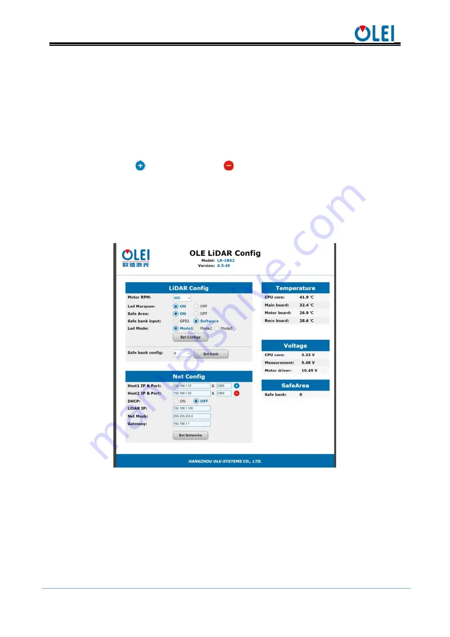
9
Set the LED indicator
ON
and
OFF
through "
Led Marquee
", and click "
Set
Configs
" to confirm;
Set the
ON
and
OFF
of the LiDAR safety function through "
Safe Area
", and click
"
Set Configs
" to confirm;
Select input mode of "
safe bank
" trough "
Safe bank input
";
Set the mode of the LED indicator through "
Led Mode
";
Select current Bank through "
Safe bank config
" when "
Safe bank input
" is
“
Software
”;
Set receiving computer IP and port through "
Host IP & Port
".Up to 3 groups can
be set. Click
to add a group, click
to delete a group.
Enable/disable the
DHCP
function: the LiDAR dynamically obtains an IP address
from the
DHCP
server (ON), and the LiDAR needs to set up a static IP address
(OFF);
Modification of LiDAR IP: Enter the new IP into the LiDAR IP column (must be in
the same network segment as the local IP), click the "
Set Network
" to confirm, and
the modification is complete after the LiDAR is powered on again
Figure 9
Parameter configuration of web page
6.2.
Parameter configuration of filter level
The web page parameter configuration method is as follows:
Open the browser (please use
Chrome, Firefox, Edge
or other standard browsers),
enter http://LIDAR IP/advanced.html; (the factory default address is:192.168.1.100)
Over range as: Select the point that exceeds the range to output as the maximum
range or display as 0;
Weak points filter: set the strength of weak point filter ;


