


5238-E P-197
SECTION 8 LATHE AUTO-PROGRAMMING FUNCTION (LAP)
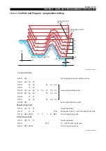
Contour definition
LE33013R0301000190002
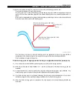
Outline of Continuous Thread Cutting Cycle in the Longitudinal Direction
(1) The commands in block N0141 select the S, T, and M commands for thread cutting.
(2) The commands in block N0142 position the axes at the AP starting point (Xs, Zs).
(3) The B, H, D, and U words in block N0143 specify the data necessary for the thread cutting
cycle.
Two types of M codes are used to select the thread cutting mode and the tool infeed pattern.
G88 NAT40 calls out the contour definition program and executes the required thread cutting
cycle (AP Mode III).
For details of the thread cutting cycle, refer to SECTION 7, "M Codes Specifying Thread Cutting
Mode and Infeed Pattern".
End Face Thread Cutting Cycle
For thread cutting on an end face, use G80 to G82 to define the thread contour, as in AP Modes I
and II. Program M27, which selects the X-axis as the thread lead reference axis in the G34/G35/
G112/G113 block. Stock removal is specified by a W word instead of a U word.
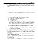
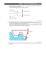
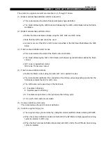
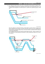
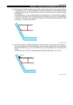
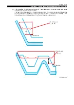
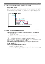
10-4. AP Mode IV (High-speed Bar Turning Cycle)
[Function]
In the AP Mode IV the blank material shape data is input in addition to the finish contour shape data.
The blank material shape is programmed in the blocks starting with G83.
The area between the blank material shape and the finish contour is cut by shifting the cutting level
by depth of cut D.
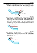
The OSP recognizes where blank material will be encountered, and the cutting tool is fed at the
rapid feedrate in areas where there is no blank material and cutting is not required. This eliminates
the cutting feed in areas that do not need to be cut, which occurs with AP Mode I , and allows high-
speed cutting.
B
: Tip point angle of thread cutting tool
H
: Height of thread to be cut
D
: Depth of cut
U
: Stock removal for finish cut
NAT40
N0401
N0402
N0403
N0404
N0405
N0141
N0142
N0143
G81
G00
G34
G01
G80
G00
G88
Xa
Xb
Xc
Xd
Xs
NAT40
Za
Zb
Zc
Zd
Zs
E
S
F
T
J
M
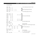
Longitudinal contour definition
End of contour definition
.............................................................................
.............................................................................
Programming Calling for Thread Cutting Cycle
M32(M33, M34) M73(M74, M75) B H D U


