background image

- 83 -

Adjusting the paper sensor (Sensor calibration)

If the paper mark cannot be detected or a paper jam often occurs, perform sensor calibration 
by the following procedure.
Adjust the paper sensor to the appropriate position for the paper to be used.

•  For the detailed procedure, refer to 

"Aligning the paper sensor" (Page 68)

.

•  Correct adjustment is not possible unless the paper sensor is properly positioned.

Check that "READY TO PRINT" appears on the display of the machine.

On the PC, click [Start], and select [Control Panel] from [Windows System 

tools].

Click [View devices and printers].

Right-click on the [Pro330S PCL6] icon, and select [Printing preferences].

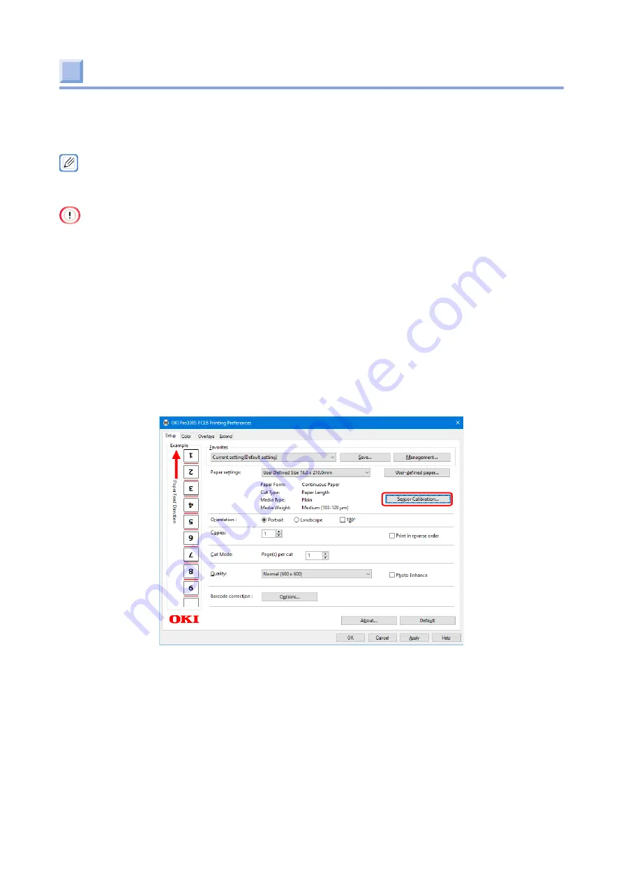
Click [Sensor Calibration...] in the [Setup] tab.

When [Would you like to execute sensor calibration?] is displayed, remove 

the paper from the machine.

Click [Execute] in the printer driver screen of your PC.

When [PLEASE LOAD PAPER] appears on the display of the machine, load 

paper in the machine.

When "READY TO PRINT" is displayed, it indicates that the process is 

completed.

Summary of Contents for PRO330S

Page 1: ...Pro330S Label Printing Manual ...

Page 2: ...ing the roll paper holder to the main unit 27 Removing the roll paper holder from the main unit 30 3 Setting up 31 Turning the power on off 32 About the power supply 32 Turning the power on 33 Turning the power off 34 Installing optional accessories 35 Installing the wireless LAN module 35 Installing the presenter unit 38 Connecting the LAN cable 42 Connecting via a wireless LAN 44 Preparing to co...

Page 3: ...r error code 380 390 when a paper jam occurs to the cutter 95 Troubleshooting for printing results 97 List of troubles with printing results 97 White streaks appear in the vertical direction 98 Horizontal white streaks appear in the paper feed direction periodically 98 Printing is faint in the vertical direction 99 Printing is light 99 White dots or lines appear 100 Condensation occurs on printed ...

Page 4: ... Cleaning the surface of the roll paper holder 112 Cleaning the inside of the roll paper holder 113 Cleaning the main unit 115 Cleaning the surface of the main unit 115 Cleaning the paper transfer roller of the main unit 116 Cleaning the paper feed roller of the main unit 123 Cleaning the paper sensor 124 Cleaning the LED head 125 Cleaning the fuser unit 127 Cleaning the cutter unit 129 Cleaning t...

Page 5: ...1 Safety precautions 6 General precautions 7 About this manual 9 About the description 10 Getting started ...

Page 6: ... 6 Safety precautions WARNING Mishandling due to ignoring this indication may cause major injuries or even death CAUTION Mishandling due to ignoring this indication may cause personal injury ...

Page 7: ... cause electric shock fire or injury Do not disassemble the machine or perform any operations other than those specified in the User s Manual Failure to do so may cause electric shock fire or injury Disconnect the power plug from the outlet and contact your dealer if the machine is dropped or the cover is damaged Failure to do so may cause electric shock fire or injury Periodically disconnect the ...

Page 8: ... Manual Failure to do so may cause a fire Operations using an uninterruptible power supply UPS or an inverter are not guaranteed Do not use an uninterruptible power supply or inverter Failure to do so may cause a fire CAUTION Do not approach the paper discharger when the power is on or during printing Doing so may cause injury Do not touch a broken liquid crystal display Doing so may cause injury ...

Page 9: ...content of this manual as complete as possible However should you notice any errors omissions or other problems contact the retail store where you made the purchase Notwithstanding the foregoing we shall not have any liability in regard to any operational effect related to the instructions contained in this manual Copyrights All rights belong to Oki Electric Industry Co Ltd This manual may not be ...

Page 10: ...ems Please read them to learn the detailed information About symbols This section describes the symbols used in this manual and their meanings Symbols Meaning Indicates buttons keys on the operator panel of this machine Indicates menu names item names options etc displayed on the operator panel Indicates menus windows and dialog box names displayed on the PC screen Indicates messages and input tex...

Page 11: ...tion 12 Unpacking 14 Checking the accessories 16 Installing consumables 20 Assembling the holder 24 Attaching the roll paper holder to the main unit 27 Removing the roll paper holder from the main unit 30 Installation ...

Page 12: ...where chemical reactions occur e g laboratories Do not install it close to combustible solutions such as alcohol and thinners Do not install it within the reach of children or infants Do not install it in an unstable location e g an unsteady table or an inclined surface Do not install it in a humid or dusty place or in a place exposed to direct sunlight Do not install it in an environment with sal...

Page 13: ...he optional roll paper holder to the main unit Install this machine on a flat desk large enough to support its base Allow sufficient space around this machine as shown in the following figures Plan view 0mm 0mm 100mm 198mm 311mm 380mm Random Side view 439mm 232mm 195mm 253mm 448mm ...

Page 14: ... this machine Keep them properly instead of discarding them 1 Take out this machine out of the packing case and remove the buffer materials and the plastic bag 2 Lift the machine and place it in the installation location For details about the installation location see About installation Page 12 ...

Page 15: ...packing case and buffer materials are required to ship the roll paper holder Keep them properly instead of discarding them 1 Open the top cover of the packing box and take out the stand plates x2 and shaft x1 2 Take the stand out of the bag and remove the accessories and ground pins ...

Page 16: ...d correctly or the accessories may not be usable later Main unit Toner cartridge The number of printable pages of a toner cartridge is approximately 5 000 which is the reference value in our in house test of printing 25 4 mm 1 inch black square blocks on 216 mm x 58 mm paper Guide rib x4 x 4 The guide rib is a part that prevents the front edge of the paper from falling into the gap near the paper ...

Page 17: ... LAN cables and USB cables are not supplied Please prepare them separately according to the connection environment The packing case buffer materials and toner covers are required to ship this machine Keep them properly instead of discarding them ...

Page 18: ... of the roll paper holder The roll paper holder is sold separately Make sure that you have all the accessories supplied with the machine Stand Plate x2 Flange lock x2 Flange large 3 inches x2 Flange small 2 inches x2 ...

Page 19: ... 19 Shaft x1 Ground pin Roll Paper Holder Setup Guide ...

Page 20: ...the glossy cylinder can easily get damaged handle with adequate care Do not expose the image drum to direct sunlight or strong light approx 1 500 lux or above Do not leave it uncovered for more than 5 minutes even under room lighting 1 Put your finger inside the recess on the top of the machine and pull the lever up 2 Open the top cover until it stops ...

Page 21: ... 21 3 Remove the protective tape 4 Remove the protective tape and the desiccant 5 Remove the toner cover Toner covers are required to ship this machine Keep them properly instead of discarding them ...

Page 22: ... 22 6 Close the top cover 7 Open the toner cartridge cover 8 Take the toner cartridge out of its packaging and shake it several times vertically and horizontally ...

Page 23: ... 23 9 Attach the toner cartridge to be installed on the machine 10 Install the toner cartridge 11 Close the toner cartridge cover ...

Page 24: ... kinds of roll paper The flanges are not attached to the plates of the holder when they are unpacked Select the flange large or flange small according to the inner diameter of the roll paper to be used and start from Step 4 This section takes the example of changing from the flange large to the flange small The paper width guide is in the minimum size position when it is unpacked Fit it to the wid...

Page 25: ...th flanges rotate the flange lock to remove the flange large 3 inches from the plate Flange large 3 inches Plate Flange lock 4 Prepare a flange small 2 inches 5 Attach the flange small 2 inches to the plate and rotate the flange lock to assemble the plate and flange Flange small 2 inches Plate Flange lock ...

Page 26: ... 26 6 Similarly assemble the other plate and flange 7 Attach both plates with flanges to the shaft Shaft Plate with flange 8 Attach the holder to the stand Holder Stand ...

Page 27: ...oll paper holder Be careful not to get your fingers or hands caught between the main unit and the roll paper holder If you bring a magnetic recording medium like a magnetic card close to the magnet part of the fixing pin of the roll paper holder the data may be corrupted and unusable 1 Insert while rotating the ground pin into the screw hole on the metal plate on the back of the printer Ground pin...

Page 28: ...nsert the ground cable into the ground pin and insert the fixing pin into the fixing hole of the main unit If the wireless LAN module is connected be careful not to pinch the wireless LAN module with the roll paper holder Fixing hole Fixing hole Ground pin Ground cable Fixing pin Fixing pin ...

Page 29: ...er on the stand Push the holder all the way into the groove of the paper width guide Be careful not to pinch your fingers or hands when installing the holder Now you have completed the installation of the roll paper holder ...

Page 30: ...l paper holder from the main unit Remove the roll paper holder from the main unit 1 Remove the stand from the main unit and disconnect the ground cable from the ground pin Ground cable 2 Remove the stand from the main unit ...

Page 31: ...2 Installing optional accessories 35 Connecting the LAN cable 42 Connecting via a wireless LAN 44 Using wired LAN and wireless LAN at the same time 50 Connecting the USB cable 51 Installing the printer driver on a PC 52 Setting up ...

Page 32: ...ed on and do not place anything on the power cord Do not bundle or bind the power cord in use Do not use a damaged power cord Do not overload the outlet Do not connect this machine and any other electric appliances to the same outlet In particular if this machine shares a same outlet with an air conditioner copier shredder etc this machine may malfunction due to electrical noise If this machine ha...

Page 33: ...power on 1 Plug the power cord to the power connector on the back of the machine 2 Insert the power plug into the outlet 3 Open the left cover on the front and press and hold the power switch for approximately 1 second ...

Page 34: ...d 2 After SHUTTING DOWN PLEASE WAIT TURN OFF AUTOMATICALLY appears on the operator panel wait until the operator panel goes off 3 Disconnect the power plug from the outlet 4 Unplug the power cord from the power connector on the back of the machine To force a shutdown press and hold the power switch for more than 5 seconds ...

Page 35: ...r without completely ejecting it Installing the wireless LAN module Install it when you want to connect this machine with a PC via a wireless LAN 1 Power off the machine Refer to Turning the power off Page 34 for details on how to turn the power off 2 Insert the wireless LAN module into the connector on the side of this machine When connecting the roll paper holder be careful not to pinch the wire...

Page 36: ...chine 4 Press and hold OK on the operator panel to power on the machine Press and hold OK until BOOT MENU appears on the display 5 When BOOT MENU appears release your finger and press OK again 6 When ENTER PASSWORD appears input the password The default password is 999999 ...

Page 37: ...d press OK 8 Press or to display WIRELESS MODULE and press OK 9 Press or to display ENABLE and press OK is displayed to the right side of the bottom 10 If you press ONLINE the machine restarts and returns to the standby state READY TO PRINT ...

Page 38: ...port without ejecting it After installing the presenter unit set the presenter unit to ENABLE on the operator panel Installing the presenter unit 1 Power off the machine Refer to Turning the power off Page 34 for details on how to turn the power off 2 Remove the connector cover 3 Remove the gear cover ...

Page 39: ... 39 4 Remove the cap labels x2 5 Insert the presenter unit into the machine Be noted that it is not completely retained 6 Tighten it with screws x2 ...

Page 40: ...onnector 8 Install the cable cover 9 Install the cap cover x2 Enabling the presenter unit on the operator panel 1 Turn on power of the machine For details on how to turn on the power refer to Turning the power on Page 33 ...

Page 41: ...ord is 999999 6 After you have input the password press OK 7 Press or several times to display OTHERS SETUP 8 Press OK 9 Press or several times to display PRESENTER UNIT 10 Press OK 11 When the setting value flashes press or to display ENABLE and press OK 12 The machine restarts and returns to the standby state READY TO PRINT For details on how to print refer to Pro330S User s Manual ...

Page 42: ... a LAN cable and a hub The machine does not come with any LAN cables Prepare a LAN cable category 5 or above twisted pair straight separately 2 Check that both the machine and the PC are powered off 3 Plug one end of the LAN cable into the network interface connector of this machine 4 Plug the other end of the LAN cable to the hub Insert it into the network interface connector of the hub ...

Page 43: ...ER PASSWORD is displayed The default password is 999999 8 After you have input the password press OK 9 Press or several times to display NETWORK SETUP and press OK 10 Press or several times to display IP ADDRESS SET and press OK 11 Press or several times to display AUTO or MANUAL and press OK If MANUAL is selected press and manually input the IPv4 address subnet mask and gateway address ...

Page 44: ...eck that your wireless device supports the following environment Standard IEEE 802 11 b g n Security WPA2 PSK AES 2 Check that your wireless device supports WPS PBC Push Button Configuration If you are not sure whether WPS PBC is supported connect manually after turning on the power of this machine Connecting via an access point Infrastructure Select the enabled default gateway 1 Press or several ...

Page 45: ... OK 7 When IT IS NOT POSSIBLE TO USE WIRELESS AP MODE AT THE SAME TIME PLEASE BE DISABLED IF THE WIRELESS AP MODE IS ENABLED PRESS OK appears press OK 8 When WIRELESS INFRASTRUCTURE is displayed press or to select ENABLE and then press OK 9 Press or several times to display WPS SETUP and press OK 10 Select WPS PBC and press OK 11 Select YES and press OK 12 When WIRELESS STARTED appears the machine...

Page 46: ...s to display AUTO or MANUAL and press OK If MANUAL is selected press and manually input the IPv4 address subnet mask and gateway address Connecting by selecting a wireless LAN access point from the opera tor panel When the wireless LAN access point does not support WPS or when WPS connection does not function well connect by specifying the wireless access point to be used from the list of wireless...

Page 47: ...ected wireless LAN access point is displayed input the encryption key recorded in Step 1 and press OK 12 The SSID selected in Step 10 and the encryption method are displayed as security on the confirmation screen If the SSID and the encryption method are the same as those recorded in Step 1 press OK 13 When SUCCESSED is displayed press OK to return to the standby state READY TO PRINT 14 If an ante...

Page 48: ...mes to select MANUAL SETUP at the bottom of the list and then press OK 11 Check that SSID is selected and then press OK 12 Input the SSID recorded in Step 1 and then press OK 13 Press to select SECURITY and then press OK 14 Select the encryption method recorded in Step 1 and then press OK The encryption key varies with the wireless LAN access point and security method 15 Press several times to sel...

Page 49: ... password when ENTER PASSWORD is displayed The default password is 999999 5 After you have input the password press OK 6 When IT IS NOT POSSIBLE TO USE WIRELESS INFRASTRUCTURE AT THE SAME TIME PLEASE BE DISABLED IF THE WIRELESS INFRASTRUCTURE IS ENABLED PRESS OK appears press OK 7 When WIRELESS AP MODE is displayed press or to select ENABLE and then press OK 8 When DO YOU WANT TO DISABLE THE WIREL...

Page 50: ... LAN and wireless LAN that can be used at the same time Wireless LAN Infrastructure and Wireless LAN AP mode cannot be enabled at the same time If wired LAN and wireless LAN are connected to the same subnet the communication may be unstable Enabled Disabled Connection with a LAN cable Wireless LAN Infrastructure Wireless LAN AP mode Combinations for simultaneous connection ...

Page 51: ...SB cable 2 Check that both the machine and the PC are powered off 3 Plug the B end of the USB cable into the USB interface connector of this machine Do not insert the USB cable into the network interface connector Otherwise malfunction may be caused 4 Plug the A end of the USB cable into the USB interface connector of the PC ...

Page 52: ...n Setup exe When the User account control screen is displayed click YES 4 Select your desired language from the pull down menu 5 Read the software license agreement and click Accept 6 Select either Network Wired Wireless or USB connection depending on the connection method between the PC and this machine and then click Next If Windows security alert screen is displayed click Allow access 7 Select ...

Page 53: ... 54 Paper storage 62 Preparing paper 63 Flow of loading paper 65 Setting paper information from the operator panel 66 Aligning the paper sensor 68 Loading paper 73 Aligning the TOP position of the paper 79 Paper settings ...

Page 54: ...eter 50 8 mm or 76 2 mm 2 inches or 3 inches in diameter Weight 2 4 kg or less Printing side Only the outer side Notes Roll end Roll paper should not be taped or glued to the winding core Paper joint Do not use roll paper with joints in the middle When there is liner total thickness includes liner Use paper with black marks printed with carbon ink Use paper with black marks with a reflectance of 2...

Page 55: ...ushing burrs etc on the paper cut surface Non square shaped paper or paper whose cutting angle is not right Paper with wrinkles warps corner bending waves creases tears etc Paper with staples clips ribbons tapes clasps etc Special paper such as carbon paper non carbon paper thermal paper and pressure sensitive paper Thermal transfer printer paper wet PPC paper Japanese paper copying paper inkjet p...

Page 56: ... 25 86 mm Cut length F 53 551 mm Left Right margin a 4 2 mm b 2 mm or above or 3 mm with a paper width of 86 mm Top margin c 4 2 mm d 2 mm or above Bottom margin e 6 3 mm f 2 mm or above Paper form settings Continuous paper Cut type settings Length Use conditions Assured printing range 4 2 mm or more from the top left and right edges of the paper and 6 3 mm or more from the bottom edge cut positio...

Page 57: ...width H 9 mm or above Black mark length I 2 5 13 mm Black mark pitch J 53 551 mm Cut position K 6 5 to Length of the black mark interval J Non preprintable area To avoid mis detection of black marks do not print around the marks Paper form settings Continuous paper Cut type settings If the black mark is on the surface B M FRONT If the black mark is on the back B M BACK Use conditions Please use pa...

Page 58: ...enter to right side P R 3 5 36 mm when the hole is on the right side to the paper center Distance from paper center to left side P L 3 5 29 mm when the hole is on the left side to the paper center Paper form settings CONTINUOUS PAPER Cut type settings If the hole is in the paper center CENTER HOLE If the hole is not in the paper center SIDE HOLE Use conditions If the hole is in the paper center se...

Page 59: ... 13 mm Left Right liner margin h 2 mm or above Left Right margin a 4 2 mm b 2 mm or above Top margin c 4 2 mm d 2 mm or above Bottom margin e 6 3 mm f 2 mm or above Paper form settings CONTINUOUS PAPER Cut type settings GAP Use conditions Cut at the center of the gap Set the paper sensor at 5 mm or above inward from the left and right edges of the label Assured printing range 4 2 mm or more from t...

Page 60: ... the specified paper length about 18 mm from the front edge of the paper The paper is cut based on the first valid mark detected within this range Furthermore if the cut type is a black mark and the cut position the distance from the black mark to the paper cut is set the mark detection range moves by the specified cut position Front edge of paper Front edge of paper Approx 18 mm Approx 18 mm Appr...

Page 61: ... enough to print the data Remaining paper length Printed paper length The print data will be printed normally and the process will exit When the remaining paper is longer than the print data When the rear edge of the paper exceeds the paper detection sensor in the paper insertion slot during operation Remaining paper length Printed paper length Printed paper length Cut position The print data will...

Page 62: ...ces where static electricity is generated Places with extreme rises and sudden fluctuations in temperature Places near copiers air conditioners heaters ducts etc Do not unpack the paper until you are ready to use it Do not leave the paper exposed to the air for a long period of time Otherwise printing failure may occur Depending on the paper type operating conditions and storage conditions the pri...

Page 63: ...e front edge Peel off the tape holding the front edge before use Do not load the roll paper with the tape attached or feed it into the machine This machine may malfunction 2 Cut the paper to the part where there are traces of tape The adhesive agent may have adhered to the traces where the tape has been peeled off If paper is fed into the machine with the adhesive section attached glue may adhere ...

Page 64: ...e of paper straight and then load the paper Do not cut it diagonally Depending on the dimensions and shape of the front edge printing may be misaligned printing may not be possible or the machine may malfunction Plain Die cut label 1 5 6 5 mm Leading liner length when loading paper Cut at the center of the gap The print position of the first sheet may shift without aligning the TOP position when c...

Page 65: ...l Page 66 Aligning the paper sensor For details see Aligning the paper sensor Page 68 Installing the guide rib For details refer to Installing the guide rib in the User s Manual of the printer Loading paper For details see Loading paper Page 73 Align the TOP position of the paper as necessary Start printing after loading the paper ...

Page 66: ...lue flashes press or to display your desired value and then press OK 6 Check that the setting value stops flashing and is displayed to the right of the value which you just set Paper size The size that can be set ranges from 25 0 mm to 86 0 mm 1 00 inch to 3 40 inch in width and from 53 0 mm to 551 mm 2 10 inch to 21 70 inch in length 7 Press once to display X DIMENSION and then press OK 8 When th...

Page 67: ... TYPE and then press OK 17 When the setting value flashes press or to display your desired value and then press OK 18 Check that the setting value stops flashing and is displayed to the right of the value which you just set 19 When LENGTH is set go to Step 23 When any other than LENGTH is set go to Step 20 Cut position This setting sets the cut position for paper with a black mark or hole When 0 m...

Page 68: ...ition the error 380 PAPER JAM may occur Reset the sensor by the following procedure 1 Turn off the power if the machine is running 2 Press and hold OK on the operator panel to power on the machine Press and hold OK until BOOT MENU appears on the display 3 When BOOT MENU appears release your finger and press OK again 4 Input the password when the password entry screen appears The password is the sa...

Page 69: ...thout marks Upper Position where it does not overlap with the lower sensor Lower Center CONTINUOUS PAPER LENGTH Cut paper Upper Position where it does not overlap with the lower sensor Lower Center CUT PAPER Die cut label without black marks Upper Center Lower Center The position where the edge of the upper lower roller is aligned with that of the sensor CONTINUOUS PAPER GAP 3 13 mm The settings o...

Page 70: ...ls on how to install the guide rib refer to Installing the guide rib in the User s Manual of the printer 1 Place your finger under the gray lever on the left side of the back of the machine and push it up to open the feeder cover 2 Insert a pointed object like a ballpoint pen into the back of the metal part of the upper sensor on the back of the feeder cover scrape it out and unlock it ...

Page 71: ...nsor into place by holding its both ends 4 Push in the metal part of the upper sensor to fix the sensor 5 Insert a pointed object like a ballpoint pen into below the metal part of the lower sensor scrape it out and unlock it ...

Page 72: ... 72 6 Move the lower sensor into place by holding its both ends 7 Push in the metal part of the lower sensor to fix the sensor 8 Close the feeder cover ...

Page 73: ... horizontally on a desk to prevent it from rolling off Do not use any paper other than the paper set for roll paper specifications If the printer is not powered on press the POWER button on the operator panel to turn on the power Attach the flange of the holder according to the inner diameter of the winding core of the roll paper For details on how to load the flange refer to Assembling the holder...

Page 74: ... Load the roll paper to the holder Insert the flange of the holder to the winding core of the roll paper Flange Winding core Flange 5 Release the lock levers of both paper width guides Lock lever Lock lever ...

Page 75: ... width guide Paper width guide Width adjustment knob Align the edges of the paper width guide with the scale Scale 7 Rotate the lock levers of both paper width guides to lock them Before locking load the roll paper and make sure there is no gap between the paper width guide and the flange If there is a gap rotate the width adjustment knob accordingly until there is no gap Lock lever Width adjustme...

Page 76: ...aper width guide Be careful not to pinch your fingers or hands when installing the holder 9 Place your finger under the gray lever on the left side of the back of the machine and push it up to open the feeder cover 10 Lift the paper guide lever on the left side of the machine to unlock it ...

Page 77: ...er guide with the width of the paper Adjust it properly until there is no gap between the paper guide and the paper 12 Tilt the paper guide lever toward you to lock it 13 Close the feeder cover right after removing the paper ...

Page 78: ... 78 14 Pass the roll paper from the bottom of the guide roller and insert it into the paper insertion slot of the printer until the roll paper stops Now the roll paper has been loaded ...

Page 79: ... changed If the front edge of paper becomes dirty you can cut off the dirty part while the paper is still loaded in the machine by aligning the TOP position of the paper If the type of paper has changed calibrate the sensor 1 Make sure that paper has been loaded in the machine 2 Check that READY TO PRINT appears on the display 3 Press FEED CUT If a paper jam occurs during printing the paper jam co...

Page 80: ...5 Registering paper information in the printer driver 81 Adjusting the paper sensor Sensor calibration 83 Changing color settings 85 Printing ...

Page 81: ...and printers 3 Right click on the Pro330S PCL6 icon and select Printing preferences 4 Click User defined paper in the Setup tab 5 Input the information of the paper to be registered 1 Select New paper from Registered user defined paper 2 Input the paper name in the Paper Name field 3 Select a suitable paper form for the paper to be used 4 Select a suitable cut type for the paper to be used ...

Page 82: ...n of the first decimal place 3 Subtract the gap length from the length calculated in 2 and calculate the label length of one label with the precision of the first decimal place For die cut labels input the value calculated in 3 in Label length and the gap length in Gap Length 6 If necessary input other information 1 If you want to make fine adjustments to the cut position of the paper input the am...

Page 83: ...k that READY TO PRINT appears on the display of the machine 2 On the PC click Start and select Control Panel from Windows System tools 3 Click View devices and printers 4 Right click on the Pro330S PCL6 icon and select Printing preferences 5 Click Sensor Calibration in the Setup tab 6 When Would you like to execute sensor calibration is displayed remove the paper from the machine 7 Click Execute i...

Page 84: ...f the machine or if there is print data in the machine If no paper is loaded within 1 minute after PLEASE LOAD PAPER is displayed an execution error will occur The execution error can be cleared by opening and closing the cover It is recommended to perform sensor calibration when changing the paper to be used ...

Page 85: ...e value in Color Mode of the Color tab Automatic Color matching shall be done depending on the specific document In general use this setting Simple Adjustment Make simple adjustments such as color matching contrast and brightness No Color Matching Prints with the specified color without color tuning Select it if color matching is done from an application 5 Click OK 6 Click Print ...

Page 86: ...6 When the LED indicator lights up 87 When a paper jam occurs 88 Troubleshooting for printing results 97 Output position shifts 107 Paper does not feed well 108 Troubleshooting ...

Page 87: ...roblem occurs to this machine the ERROR or WARNING LED indicator will light on or flash and a message will appear on the display Take an action as indicated by the message For a list of messages refer to Message List in the Pro330S User s Manual ...

Page 88: ...nit 1 When the paper is jammed cut the paper with scissors near the paper insertion slot 2 Put your finger inside the recess on the top of the machine and pull the lever up 3 Open the top cover until it stops CAUTION Otherwise burns may be caused Do not touch the fuser unit because it is hot ...

Page 89: ...t out 5 Place the removed image drum on a flat surface and cover it with newspaper or the like to avoid direct light 6 When the front edge is visible slowly pull out the paper towards you If paper is jammed in the fuser unit refer to For error code 382 when a paper jam occurs to the fuser unit Page 91 ...

Page 90: ... 90 7 Install the image drum back to the machine 8 Close the top cover ...

Page 91: ...paper is jammed cut the paper with scissors near the paper insertion slot 2 Put your finger inside the recess on the top of the machine and pull the lever up 3 Open the top cover until it stops CAUTION Otherwise burns may be caused Do not touch the fuser unit because it is hot ...

Page 92: ...e removed image drum on a flat surface and cover it with newspaper or the like to avoid direct light 6 Remove the fuser unit CAUTION Otherwise burns may be caused As the fuser unit may be hot be cautious during operation and always hold the handle to lift it When it is hot wait until it cools down before any operation ...

Page 93: ...direction opposite to the paper travel direction 8 Align the red on the right side of the fuser unit with the red inside the machine lower it vertically and return it to its original position inside the machine 9 Tilt the blue handle of the fuser unit toward you to store ...

Page 94: ... 94 10 Install the image drum back to the machine 11 Close the top cover ...

Page 95: ... 390 when a paper jam oc curs to the cutter 1 The back of the machine should be facing you 2 Place your finger under the gray lever on the left side and push it up to open the feeder cover 3 Slowly pull out the jammed paper ...

Page 96: ...hine on the operator panel and adjust the position of the paper sensor accordingly Aligning the paper sensor Page 68 If error code 380 persists even after you have execute the above operations execute SENSOR RESET in the BOOT MENU by the following procedure 1 Turn off the power if the machine is running 2 Press and hold OK on the operator panel to power on the machine Press and hold OK until BOOT ...

Page 97: ...ondensation occurs on printed paper Vertical streaks appear Dots and horizontal streaks appear in the paper feeding direction periodical ly White area is lightly stained Paper feed direction Paper feed direction Edges of text are blurred Toner comes off due to rubbing Specks appear on glossy paper Black or white dots appear Stains are printed The entire paper is printed in black Nothing is printed...

Page 98: ...e drum Replacing the image drum Pro330S User s Manual Horizontal white streaks appear in the paper feed direction periodically Possible causes Solution Reference The image drum is not installed correctly Please install the image drum correctly Replacing the image drum Pro330S User s Manual The image drum is dirty Turn on the drum cleaning However when it is turned on the service life of the image ...

Page 99: ...edia weight is set incorrectly Set an appropriate value for Media Weight in the user defined paper settings of the printer driver Alternatively increase the setting value for Media Weight If you do not use the printer driver click MENUS FEEDER CONFIG MEDIAWEIGHT on the operator panel and set an appropriate value Alternatively increase the setting value for MEDIAWEIGHT Loading paper Registering pap...

Page 100: ...dity Loading paper This machine is used in a place with high humidity or sudden changes in temperature and humidity Use this machine in an environment with an appropriate temperature and humidity About installation Vertical streaks appear Possible causes Solution Reference The image drum is scratched Please replace the image drum Replacing the image drum Pro330S User s Manual The paper transfer pa...

Page 101: ...rinter idle for a few hours If the problem persists replace the image drum Replacing the image drum Pro330S User s Manual Dirt adheres to the paper transfer path Clean the paper transfer system Cleaning White area is lightly stained Possible causes Solution Reference Static electricity occurs to the paper Use the paper stored at appropriate temperature and humidity Loading paper Thick paper is use...

Page 102: ...pplicable paper Toner comes off due to rubbing Possible causes Solution Reference The media weight is set incorrectly Set an appropriate value for Media Weight in the user defined paper settings of the printer driver Alternatively increase the setting value for Media Weight If you do not use the printer driver click MENUS FEEDER CONFIG MEDIAWEIGHT on the operator panel and set an appropriate value...

Page 103: ...le causes Solution Reference If the interval is approximately 63 mm the green tube of the image drum is scratched or dirty Gently wipe it with soft tissue paper Replace the image drum if it is damaged Replacing the image drum Pro330S User s Manual If the interval is approximately 26 mm dirt enters the charging roller inside the image drum Open and close the top cover or feeder cover and print agai...

Page 104: ...paper is moist Replace with new paper Loading paper If they occur near the beginning of the roll paper the tape holding the roll paper may have peeled off Cut off the front edge of the paper to the part where there are traces of tape and discard it Preparing paper The peripheral area is dirty Possible causes Solution Reference The size is not reduced by scale according to the paper size Reduce the...

Page 105: ... top cover Alternatively execute CALIBRATION ADJUST REGISTRATION from the menu Parts identification Pro330S User s Manual Menu list Pro330S User s Manual Replace mono barcode with cyan is turned on Open the Setup tab in the printer driver and uncheck Barcode correction Options Replace mono barcode with cyan Printing with barcode calibrated Pro330S User s Manual The bar width adjustment is enabled ...

Page 106: ...0 255 255 and specify Automatic in the color menu of the printer driver before printing If the color of the barcode 2D code is fixed to black check Replace mono barcode with cyan in Barcode correction of the printer driver before printing Printing with barcode calibrated Pro330S User s Manual The bar is too thick Turn off Adjust ultra fine lines in Advanced of the printer driver If you can make ad...

Page 107: ...er size in the printer driver Page 81 The position of the black mark sensor or the gap sensor is misaligned Adjust the sensor position according to the paper form Page 68 It is exposed from the rear edge of the paper The paper size set in the printer driver is different from the size of the paper loaded Specify a correct paper size in the printer driver Page 81 The rightmost output position is mis...

Page 108: ...cutting the gap between labels Cut it in the correct position of the front edge and load the paper again Page 63 The paper sensor is not adjusted correctly Calibrate the sensor again Page 83 The paper width guide does not match the width of the paper to be used Adjust the paper width guide to the width of the paper to be used The loaded paper is not suitable Change the settings in the printer driv...

Page 109: ... panel Alternatively set a thinner value for MEDIAWEIGHT Page 66 Paper winds around the roller of the fuser unit The paper type and weight is set incorrectly Set an appropriate value for Media Weight in the userdefined paper settings of the printer driver If you do not use the printer driver click MENUS FEEDER CONFIG MEDIAWEIGHT on the operator panel and set an appropriate value Page 66 Thin paper...

Page 110: ...7 Cleaning 111 Cleaning the roll paper holder 112 Cleaning the main unit 115 Maintenance ...

Page 111: ...iver It is used when the cutter unit is to be cleaned Cleaning cycle Check the condition of the machine and clean it if necessary before and after each use The following table lists the guideline for cleaning Cleaning cycle Reference page s Daily Whenever dirt is noticeable Roll paper holder Surface Page 112 Flange Page 113 Guide roller Main unit Surface Page 116 Transfer roller Page 116 Sensor co...

Page 112: ...utral detergent It is not necessary to oil the roll paper holder Do not lubricate 1 Open the left cover on the front and press and hold the power switch for approximately 1 second After a while the LED indicator of the POWER button will light off 2 After SHUTTING DOWN PLEASE WAIT TURN OFF AUTOMATICALLY appears on the operator panel wait until the operator panel goes off 3 Clean it with a cloth sli...

Page 113: ...d press and hold the power switch for approximately 1 second After a while the LED indicator of the POWER button will light off 2 After SHUTTING DOWN PLEASE WAIT TURN OFF AUTOMATICALLY appears on the operator panel wait until the operator panel goes off 3 Remove the holder from the stand ...

Page 114: ...free of water Plate Flange Flange Side Side Plate 6 While rotating the guide roller wipe the dirt on the guide roller in one direction with a soft cloth moistened with the wiping solution free of water Guide roller Reference For details on how to clean the cutter unit refer to Cleaning the cutter unit Page 129 7 Load the roll paper Reference For details on how to load the roll paper refer to Loadi...

Page 115: ...ry to oil the machine Do not lubricate 1 Open the left cover on the front and press and hold the power switch for approximately 1 second After a while the LED indicator of the POWER button will light off 2 After SHUTTING DOWN PLEASE WAIT TURN OFF AUTOMATICALLY appears on the operator panel wait until the operator panel goes off 3 Clean the surface of this machine with a cloth slightly moistened wi...

Page 116: ...ower switch for approximately 1 second After a while the LED indicator of the POWER button will light off 3 After SHUTTING DOWN PLEASE WAIT TURN OFF AUTOMATICALLY appears on the operator panel wait until the operator panel goes off 4 Disconnect the power plug from the outlet 5 Unplug the power cord from the power connector on the back of the machine ...

Page 117: ...e lever up 7 Open the top cover until it stops CAUTION Otherwise burns may be caused Do not touch the fuser unit until it cools down because it is hot immediately after printing 8 Hold the blue handle and pull out the image drum vertically Open the top cover before pulling it out ...

Page 118: ...ver it with newspaper or the like to avoid direct light 10 Pull the belt unit out vertically by holding its handle black 11 Put your fingers in the recess at both ends in the rear side of the machine and at the bottom center and tilt the sensor lever towards you ...

Page 119: ... inside the machine inward to unlock 13 Take the paper transfer roller out by holding its left and right knobs white and black 14 Wipe the entire surface of the removed paper transfer roller with a cloth slightly moistened with water ...

Page 120: ...aning Install it properly while keeping it on the same side as the blue lock 16 Slide the blue lever x2 inside the machine outward to lock the paper transfer roller Lock the blue lock over the left handle so that the blue lock hangs over the black handle on the right side ...

Page 121: ... 121 17 Push the sensor lever into the main unit Install it back to its original position 18 Install the belt unit back to the machine 19 Install the image drum back to the machine ...

Page 122: ... 122 20 Close the top cover ...

Page 123: ... machine should be facing you 3 Place your finger under the gray lever on the left side and push it up to open the feeder cover 4 Check if paper dust or glue from the label adheres to the paper feed roller If so wipe the paper feed roller with a soft cloth moistened with the wiping solution free of water ...

Page 124: ...The back of the machine should be facing you 3 Place your finger under the gray lever on the left side and push it up to open the feeder cover 4 Check if any paper dust adheres to the lens of the paper sensor Gently wipe the paper dust if any off with a soft dry cloth ...

Page 125: ...ur Do not use methyl alcohol or thinner Otherwise the LED head may be damaged Do not expose the image drum to direct sunlight or strong light approx 1 500 lux or above To leave it even under indoor lighting for more than 5 minutes or to leave the top cover open be careful to cover it with a black cloth or newspaper to avoid direct light 1 Take off your watch or bracelet 2 Put your finger inside th...

Page 126: ... 4 Cover the image drum with newspaper to avoid direct light 5 Gently wipe the lens surface of the LED head x 3 with soft tissue paper 6 Remove the newspaper etc from the image drum and close the top cover ...

Page 127: ...el is changed from narrow to wide traces of the paper width paper dust etc may cause streaks during printing When the width of the label has changed check the condition of the fuser unit clean it if needed and resume printing Special cleaning paper is required for such cleaning Please consult your dealer 1 Prepare cleaning paper 2 Load the cleaning paper in the printer ...

Page 128: ...isplay CLEANING EXECUTE and then press OK Cleaning printing will start Repeat Steps 1 4 until no dirt adheres to the cleaning paper Cleaning paper cannot be reused Please dispose of the printed cleaning paper After cleaning has completed load new paper and start printing ...

Page 129: ...s clean the cutter blade Be sure to power off the printer and disconnect the power cord from the outlet before cleaning Please use the specified tools for cleaning Do not touch the cutter blade with your bare hands Otherwise injury may be caused Do not use any solvent other than the wiping solution free of water After cleaning wipe it dry Wear gloves to clean with the wiping solution free of water...

Page 130: ...off 3 After SHUTTING DOWN PLEASE WAIT TURN OFF AUTOMATICALLY appears on the operator panel wait until the operator panel goes off 4 Disconnect the power plug from the outlet 5 Unplug the power cord from the power connector on the back of the machine 6 Remove the paper roll holder Reference For details on how to remove the roll paper refer to Removing the roll paper holder from the main unit Page 3...

Page 131: ...ch the cutter blade with your hand Otherwise injury may be caused 1 The back of the machine should be facing you 2 Place your finger under the gray lever on the left side and push it up to open the feeder cover 3 With a Phillips head screwdriver loosen the screws and remove both covers R and L Screw Screw Cover R Cover L ...

Page 132: ...lever of the cutter unit upper and remove the cutter unit upper from the feeder cover Cutter unit upper 5 Lift the lock lever of the cutter unit lower and remove the cutter unit lower Lever lock Lever lock Cutter unit lower ...

Page 133: ...lution free of water left and right while pressing it against the blade on the spiral to remove the adhered glue Spiral blade Rotary blade Gear Check that there is no glue left on the cutter blade If glue remains clean the cutter blade again in the same way Check that there is no cloth lint left on the cutter blade or in the cutter unit If it remains wipe it off again with a cleaning stick After c...

Page 134: ... lower in the roll paper holder 1 Check that the lock lever of the cutter unit lower is raised and then install the cutter unit lower 2 Tilt the lock levers at both ends of the cutter unit lower Lever lock Lever lock Lever lock Lever lock ...

Page 135: ...Align the cutter unit upper with the yellow label attached onto the feeder cover 9 Close the feeder cover until you hear a click 10 Attach the roll paper holder to the main unit Reference For details on how to attach the roll paper holder refer to Attaching the roll paper holder to the main unit Page 27 The cleaning of the cutter blade is completed ...

Page 136: ...water 1 Take off your watch or bracelet 2 Open the left cover on the front and press and hold the power switch for approximately 1 second After a while the LED indicator of the POWER button will light off 3 After SHUTTING DOWN PLEASE WAIT TURN OFF AUTOMATICALLY appears on the operator panel wait until the operator panel goes off 4 Disconnect the power plug from the outlet 5 Unplug the power cord f...

Page 137: ...e lever up 7 Open the top cover until it stops CAUTION Otherwise burns may be caused Do not touch the fuser unit until it cools down because it is hot immediately after printing 8 Hold the blue handle and pull out the image drum vertically Open the top cover before pulling it out ...

Page 138: ...r it with newspaper or the like to avoid direct light 10 Pull the belt unit out vertically by holding its handle black 11 Place the belt unit on a flat surface and wipe the surface of the belt unit with a soft cloth moistened with the wiping solution free of water ...

Page 139: ... the wiping solution free of water is completely dry and then return the belt unit to the original position The machine may be damaged if it operates before the wiping solution free of water is completely dry 13 Install the image drum back to the machine 14 Close the top cover ...

Page 140: ...EE8001 5120Z002 Rev3 ...

Reviews: