background image

- 7 -


Precautions about the Installation Environment 

and Location to Install the Machine

[Precautions related to installation]

WARNING


z

Do not install the equipment in a location that is 

near open flame or may become very hot.


z

Do not install the equipment in a location prone 

to chemical reactions (laboratory, etc.).


z

Do not install the equipment in a location that is 

near flammable liquids, such as alcohol or paint 

thinner.


z

Do not install the equipment in a location that is 

accessible by small children.


z

Do not install the equipment in a location that is 

unstable (on a wobbly table or inclined place).


z

Do not install the equipment in direct sunlight or 

in a very dusty or humid location.


z

Do not install the equipment in an environment 

subject to salt air, NOx, SOx or corrosive gases.


z

Do not install the equipment in a location that is 

subject to excessive vibration.


z

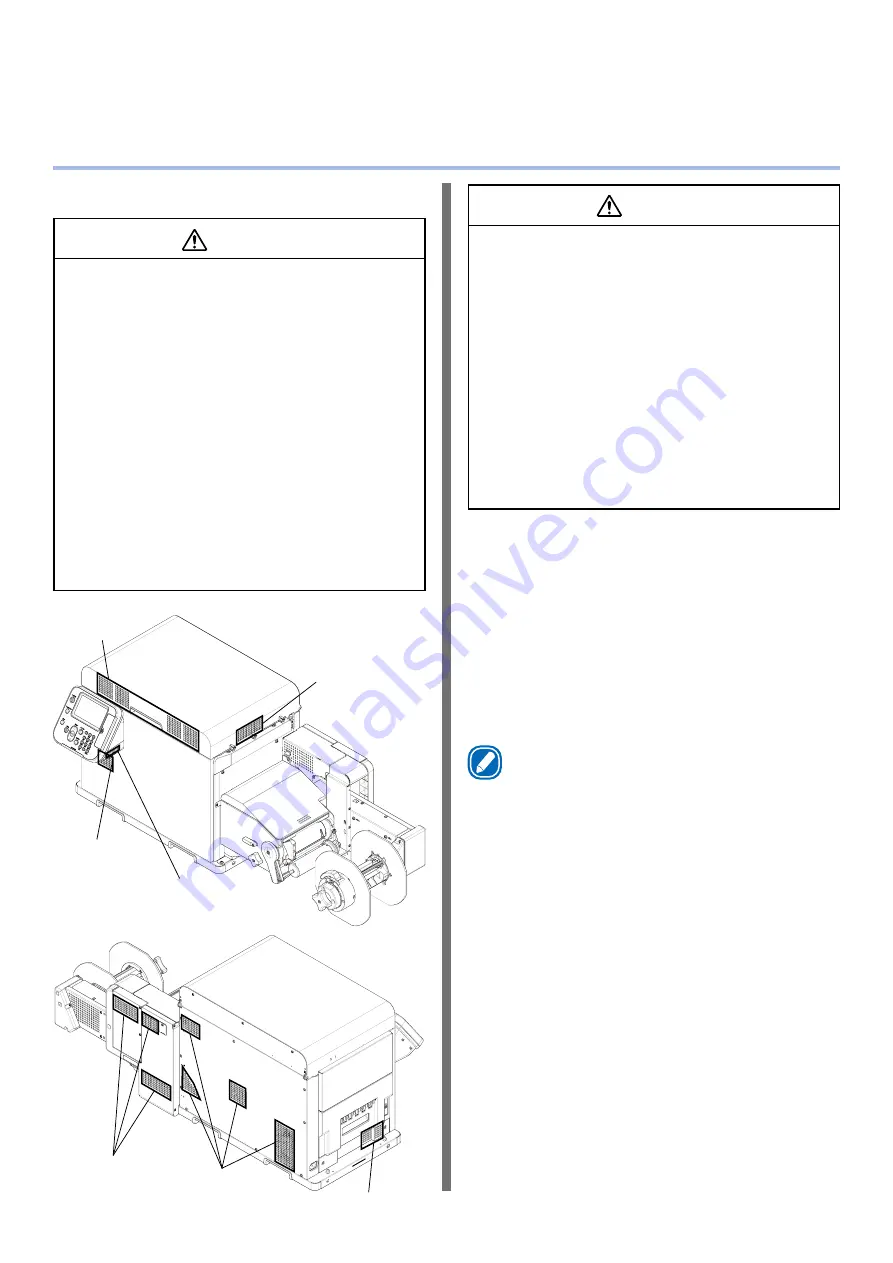
Do not install the equipment in a location where 

the machine’s vents are blocked. Check the 

positions of the vents in the following illustration.

Front of printer's 
top cover

Right side of 
printer's top 
cover

Front of printer

Control panel

Left side of printer

Back of printer

Back of unwinder

CAUTION


z

Do not install the equipment on a thick-piled 

carpet or rug.


z

Do not install the equipment in a location that is 

poorly ventilated or stuffy.


z

Pay attention to ventilation when operating the 

equipment continuously for a long period in a 

small room.


z

Install the equipment away from sources of strong 

magnetic or electric noise.


z

Install the equipment away from monitors or 

televisions.


z

Remember to use ventilation when printing large 

volumes or operating the equipment continuously 

for a long period.


z

The machine’s acoustic power level exceeds 6.3B, 

so we recommend that it be installed in a room 

separate from office work areas.

Consider the following environment conditions 

when you select the installation location.

[Installation Environment]

Use a location that is within the following ranges 

for temperature and humidity.

Temperature range:

10 to 30 ºC

Humidity range:

20 to 70% RH  

(relative humidity)

Maximum wet-bulb 

temperature:


25 ºC

Memo


z

Be careful that condensation does not form.


z

If you install the equipment in a location where the 

humidity is in a range of less than 30%, use a humidifier 

or anti-static mat.

Summary of Contents for Pro1040

Page 1: ...Pro1040 Pro1050 Setup Guide...

Page 2: ...about product functions and operations z z Maintenance Guide This manual describes how to replace consumables and how to clean and maintain the product The latest versions of the manuals can be downl...

Page 3: ...ed printer and computer connection type Select to install the standard printer driver Select to add printer drivers and select the driver you want Refer to this PDF manual to find out about useful pri...

Page 4: ...andling due to ignoring this display may cause personal injury Keys Buttons and Symbols This chapter describes the following keys buttons and symbols Notation Description button key z z Indicates hard...

Page 5: ...roducts and screens Inscriptions The following inscriptions are used in this manual z z Microsoft Windows 10 64 bit Edition operating system Windows 10 64 bit Edition z z Microsoft Windows 10 operatin...

Page 6: ...result Unplug the power plug regularly and clean the bases of and in between the plug blades If the power plug is left plugged into the outlet for an extended period of time dust adheres on the bases...

Page 7: ...Right side of printer s top cover Front of printer Control panel Left side of printer Back of printer Back of unwinder CAUTION z z Do not install the equipment on a thick piled carpet or rug z z Do n...

Page 8: ...8 External Dimensions 477 mm 1040 mm 441 mm...

Page 9: ...in an emergency z z Do not place things around the machine To install the printer and the unwinder on a stand the stand must be at least 1050 mm wide and 500 mm deep If you install the printer and the...

Page 10: ...ent herein without authorization You must obtain written permission from Oki Data Corporation before doing any of the above 2018 Oki Data Corporation OKI is a registered trademark of Oki Electric Indu...

Page 11: ...remove them then remove them Then continue washing If you drink it If you feel bad contact a physician Manufacturer Oki Data Corporation 4 11 22 Shibaura Minato ku Tokyo 108 8551 Japan For all sales...

Page 12: ...Color A powerful collection of color calibration functions The printer s control panel has functions for correcting color alignment and density in order to adjust color balance The computer based colo...

Page 13: ...etting configuration on the control panel The control panel can be used to change the paper size and to configure the network setup and other function settings The administrator password can also be s...

Page 14: ...arranty 10 Emergency First Aid 11 Manufacturer 11 Importer to the EU Authorized Representative 11 Environmental Information 11 Pro1040 Pro1050 Features 12 Parts Nomenclature and Functions 16 Printer 1...

Page 15: ...talling the Driver on a Computer 32 Operating Environment 33 Connecting Cables 34 LAN Cable Connection 34 USB Cable Connection 35 Installing the Printer Driver 36 Network Connection 36 Connecting with...

Page 16: ...and Exit Unit Remove when replacing the fuser and exit unit or when clearing a paper jam The fuser and exit unit is a consumable item Control Panel Displays the printer status and menus and is used wh...

Page 17: ...menclature and Functions Fuser and Exit Unit Handle Pull upwards when removing the fuser and exit unit Release Lever Press downwards when opening the exit feed cover Exit Feed Cover Open when clearing...

Page 18: ...by screen of the control panel 1 The print cartridge is a consumable item Belt Unit Transfers toner to the paper The belt unit is a consumable item Belt Unit Handle Grasp when removing the belt unit 1...

Page 19: ...e waste toner box is a consumable item Paper Guide Remove when a paper jam occurs in the paper transport path or when cleaning the paper transfer roller The Paper Guide is a periodically replaced part...

Page 20: ...Interface Connector For connection of a LAN cable Use this connector when connecting the printer on a network USB 2 0 Interface Connector For connection of a USB 2 0 cable Use this connector when usin...

Page 21: ...s been placed on the roll paper holder Roll Paper Holder Sets the paper to be printed Tension Bar Open Lever Keeps roll paper that has been set from sagging Flange Fixes roll paper to the roll paper h...

Page 22: ...of the paper to be printed F0 Roller Unit The F0 roller unit is a roller for feeding roll paper The F0 roller unit is a periodically replaced part Roll Paper Guide Align the roll paper guide along the...

Page 23: ...hts orange when you can refer to help messages describing the error that has occurred and providing information about how to clear the error BACK button z z Goes back to the previous screen ATTENTION...

Page 24: ...pages of the menu displayed on the LCD If there is a scroll bar it means there are menu items that are currently not visible on the LCD Press the scroll buttons and to display them A password must be...

Page 25: ...e the numeric keypad to input the administrator password The factory default password is 999999 Press the OK button after inputting each character 4 Press the OK button 5 Press the scroll button sever...

Page 26: ...ns to the standby screen ON LINE button If the error message indicates a clearable error pressing the ON LINE button returns to the standby screen CANCEL button The errors listed below can be canceled...

Page 27: ...er Enabled when standby screen is displayed When inputting a value this key is used to cycle through symbols CLEAR key When inputting a password pressing this key deletes a single character Memo z z T...

Page 28: ...Position Adjust 230 Media Transfer Setting Black 231 Media Transfer Setting Color 234 SMR Setting 235 BG Setting 236 Drum Cleaning 237 Hex Dump 238 Transfer Roller Cleaning 300 Adjust Density 301 Adj...

Page 29: ...to the same power socket as the machine The machine may malfunction due to the electronic noise particularly if you connect an air conditioner copier shredder or other device at the same time If you m...

Page 30: ...ug the power plug into the power socket Turning on the Power Supply 1 Press and hold the POWER button for approximately 1 second When the power is turned on the LED lamp on the POWER button turns on M...

Page 31: ...e machine s power automatically turns off and the LED lamp on the POWER button turns off Memo z z Pressing on the POWER button for five seconds or longer forces the power to turn off Do this only if s...

Page 32: ...have a computer with a DVD drive connected for installation Flow for Installing the Driver on a Computer Connecting to a PC Network Connection USB Connection Connect the cable Turn on the printer Set...

Page 33: ...indows 8 1 Windows 8 1 64 bit version z z Windows 8 Windows 8 64 bit version z z Windows Server 2016 z z Windows Server 2012 R2 z z Windows Server 2012 z z Windows 7 Windows 7 64 bit version z z Windo...

Page 34: ...e is routed in front of the device use the cable clamps attached to the unwinder z z Passing cable through the clamps avoids problems with unwinder operation Things to Prepare LAN cable Hub Note z z T...

Page 35: ...le 1 Taking care to orient the connector correctly connect the square end of the USB cable to the printer USB interface connector USB cable 2 Connect the other flat end of the USB cable to the compute...

Page 36: ...detailed information check with your enterprise network administrator internet service provider or router manufacturer z z PC administrator privileges are required for the setup z z Unless otherwise...

Page 37: ...en press the OK button 6 Press the scroll button several times to select IP Address Set and then press the OK button 7 To set the IP address manually press the scroll button to select Manual and then...

Page 38: ...the screen is an example Check with your enterprise network administrator for the value to actually input 10Press the scroll button to select Subnet Mask and then press the OK button 11 Input the sub...

Page 39: ...ically advance to To Install the Printer Driver P 40 1 Turn on the computer and start up Windows 2 Click Start and then select Control panel in Windows System 3 Click View network status and tasks 4 C...

Page 40: ...9 Exit the Ethernet Properties screen To Install the Printer Driver 1 Check that the printer is connected to the computer and then turn on the power Reference z z LAN Cable Connection P 34 2 Insert t...

Page 41: ...er installation is complete click Complete 10The network administrator password and the language of the control panel can be changed as necessary on this screen If changes are unnecessary or completed...

Page 42: ...rt Connecting with USB Note z z Confirm that the printer is turned off z z PC administrator privileges are required for the setup z z Unless otherwise specified operations here are shown using Windows...

Page 43: ...ftware to start installation 10After installation is complete click Complete 11 The network administrator password and the language of the control panel can be changed as necessary on this screen If c...

Page 44: ...rom the computer Note z z After installing the printer driver if you click Print Test Page in the screen below the layout of the image skews in the printed results when you print a test page which is...

Page 45: ...ems If you run into problems while setting up a network connection or USB connection refer to the attached Maintenance Guide This section describes possible problems that may occur while operating the...

Page 46: ...Oki Data Corporation 4 11 22 Shibaura Minato ku Tokyo 108 8551 Japan https www oki com printing March 2019 46938702EE Rev2...

Reviews: