background image

98

3.SETTING ITEMS (USER)

3

5. SETTING E-FILING FUNCTIONS

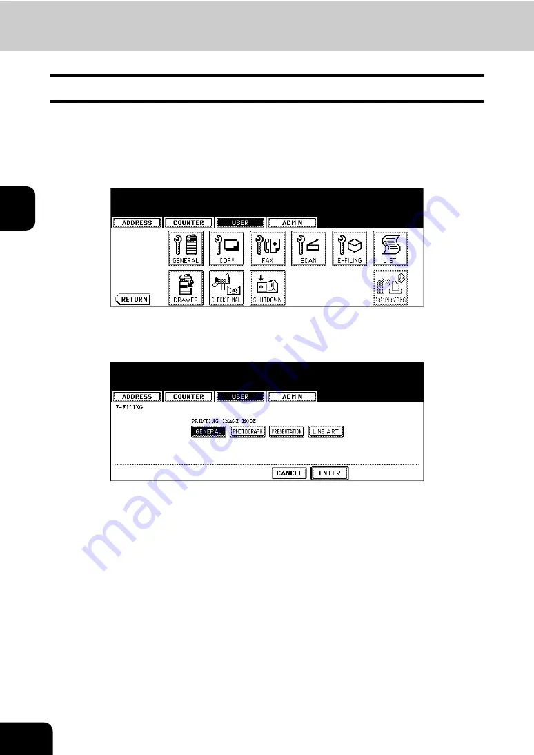
You can set the image quality type for printing color documents from e-Filing.

1

Press the [USER FUNCTIONS] button on the control panel to enter the 
User Functions menu.

2

Press the [USER] button, and then press the [E-FILING] button on the 
touch panel.

• The E-FILING screen is displayed.

3

In the “PRINTING IMAGE MODE” option, press the desired mode but-
ton.

[GENERAL]

 — Press this to apply proper color quality for printing a general color document.

[PHOTOGRAPH]

 — Press this to apply proper color quality for printing photos.

[PRESENTATION]

 — Press this to apply proper image quality for printing a vivid document.

[LINE ART]

 — Press this to apply proper image quality for printing a document contains a lot of characters or 

line arts.

4

Press the [ENTER] button.

Summary of Contents for CX 1145 MFP

Page 1: ...User Functions Guide CX1145 MFP 59315801 Rev 1 0...

Page 2: ...osoft Windows Windows NT and the brand names and product names of other Microsoft products are trademarks of Microsoft Corporation in the US and other countries Apple AppleTalk Macintosh Mac TrueType...

Page 3: ...List 50 Enabling Department Code 51 Resetting All Department Counters 53 Deleting All Department Codes 54 Registering a New Department Code 55 Editing the Department Code 58 Deleting the Department C...

Page 4: ...SETTING FAX FUNCTIONS 175 Setting the Terminal ID 175 Setting the Fax Initial Setup 178 Setting the Line 2 Mode 180 Setting the RX Printing 183 Setting the Recovery Transmission 187 6 SETTING FILE FUN...

Page 5: ...Digital System How to operate the functions in the USER FUNCTIONS button Before using the Multifunctional Digital System thoroughly read and understand this Operator s Manual To ensure that clean copi...

Page 6: ...hat may be useful for the operation of this equipment with the following signage Indicates a potentially hazardous situation which if not avoided may result in minor or moderate injury partial damage...

Page 7: ...bout Managing Contacts in Address Book 6 Registering Contacts 7 Editing Contacts 10 Deleting Contacts 12 Searching Contacts 14 2 MANAGING GROUPS 18 About Managing Groups in Address Book 18 Creating Ne...

Page 8: ...ail address or both in each contact Also you can specify the option settings for the fax transmission in each contact such as Transmission type ECM Quality transmission Line select and subaddress sett...

Page 9: ...unctions menu 2 Press the ADDRESS button and then press the ADDRESS BOOK button on the touch panel The ADDRESS BOOK screen is displayed 3 Press undefined button that you want to register new contact a...

Page 10: ...ompany name of the contact DEPT Enter the department name of the contact KEYWORD Enter the keyword of the contact This keyword can be used to search for this contact You must at least enter either the...

Page 11: ...the Quality TX or OFF button to disable the Quality TX LINE SELECT Select the line to be used for the fax transmission Press the LINE1 button to use the Line 1 or LINE2 button to use Line 2 The LINE2...

Page 12: ...ss the ADDRESS button and then press the ADDRESS BOOK button on the touch panel The ADDRESS BOOK screen is displayed 3 Press the contact that you want to edit and press the EDIT button The ADDRESS BOO...

Page 13: ...e OPTION button to specify the default settings for a fax transmission This is available only when the optional fax unit is installed 6 Specify the items as you required For the description of each it...

Page 14: ...the control panel to enter the User Functions menu 2 Press the ADDRESS button and then press the ADDRESS BOOK button on the touch panel The ADDRESS BOOK screen is displayed 3 Press the contact that yo...

Page 15: ...13 1 4 Press the YES button to delete the contact or the NO button to cancel deleting When you press the YES button the selected contact is deleted...

Page 16: ...earch for the contacts by entering an ID number or the search strings Searching a Contact by ID Number 1 Press the USER FUNCTIONS button on the control panel to enter the User Functions menu 2 Press t...

Page 17: ...tact See Editing Contacts for the instruction to edit the contact P 10 Searching Contacts by Entering Search String 1 Press the USER FUNCTIONS button on the control panel to enter the User Functions m...

Page 18: ...search string When you press each button the input screen is displayed 5 Enter the search string using the keyboard and digital keys and press the ENTER button It will search for the contacts that co...

Page 19: ...ouch panel displays the screen that contains the searched con tacts Press the contact and press the ENTER button to edit the con tact information See Editing Contacts for the instruction to edit the c...

Page 20: ...up to 200 groups and each group can contain up to 400 members One fax number or one E mail address is counted as one destination If you select the contact that contains both fax number and E mail addr...

Page 21: ...the ADDRESS button and then press the GROUP button on the touch panel The GROUP screen is displayed 3 Press undefined button that you want to create a new group and press the ENTRY button The GROUP N...

Page 22: ...ed 7 Select the contacts that you want to add to the group and then press the ENTER button To add or remove the contacts by selecting each contacts manually see Adding or Removing Contacts P 24 To add...

Page 23: ...21 1 8 New Group is created and appears on the touch panel...

Page 24: ...the USER FUNCTIONS button on the control panel to enter the User Functions menu 2 Press the ADDRESS button and then press the GROUP button on the touch panel The GROUP screen is displayed 3 Press the...

Page 25: ...screen is displayed If you do not need to change the group name press the ENTER button and then skip to step 7 5 Enter the group name using the keyboard and digital keys and press the ENTER button 6 P...

Page 26: ...ress the ENTER key to save the set tings Adding or Removing Contacts 1 Press the contacts that are not highlighted to add to the group or press the highlighted contacts to remove from the group To add...

Page 27: ...to be added to the group To add both the fax number and E mail address of a contact to the group press over the contact name To add only the fax number of a contact to the group press the FAX button...

Page 28: ...h String 1 Press the SEARCH ADDRESS button The SEARCH ADDRESS screen is displayed 2 Press the button that is used for searching to specify the search string When you press each button the input screen...

Page 29: ...fax number and E mail address of a contact to the group press over the contact name To add only the fax number of a contact to the group press the FAX button of the contact To add only the E mail add...

Page 30: ...the control panel to enter the User Functions menu 2 Press the ADDRESS button and then press the GROUP button on the touch panel The GROUP screen is displayed 3 Press the group that you want to delet...

Page 31: ...29 1 4 Press the YES button to delete the contact or NO button to cancel deleting When you press the YES button the selected group is deleted...

Page 32: ...an search for the groups by entering the ID number or the search string Searching a Group by ID Number 1 Press the USER FUNCTIONS button on the control panel to enter the User Functions menu 2 Press t...

Page 33: ...diting Groups for the instruction to edit the group P 22 Searching Groups by Group Name 1 Press the USER FUNCTIONS button on the control panel to enter the User Functions menu 2 Press the ADDRESS butt...

Page 34: ...GROUP NAME button to specify the search string The input screen is displayed 5 Enter the search string using the keyboard and digital keys and press the ENTER button It will search for the groups that...

Page 35: ...The touch panel displays the screen that contains the searched groups Press the group and press the ENTER button to edit the group information See Editing Groups for the instruction to edit the contac...

Page 36: ...ntacts that are added in the group 1 Press the USER FUNCTIONS button on the control panel to enter the User Functions menu 2 Press the ADDRESS button and then press the GROUP button on the touch panel...

Page 37: ...unication Counter for Department Code 46 4 MANAGING DEPARTMENT CODE 48 Logging On As Administrator 48 Printing Department Codes List 50 Enabling Department Code 51 Resetting All Department Counters 53...

Page 38: ...by fax receptions Printer Counter indicates the number of sheets that have been printed by print operations and E mail receptions Internet Fax receptions List Counter indicates the number of sheets th...

Page 39: ...isplay the total number of copies classified by size group 6 Press the FAX button to display the total number of faxes classified by size group 7 Press the PRINTER button to display the total number o...

Page 40: ...38 2 MANAGING COUNTERS COUNTER MENU 1 TOTAL COUNTER Cont 2 8 Press the LIST button to display the total number of printed lists classified by size group...

Page 41: ...ber of originals that have been scanned by fax and Internet Fax transmissions Network Counter indicates the number of originals that have been scanned by scan operations 1 Press the USER FUNCTIONS but...

Page 42: ...counter list 1 Press the USER FUNCTIONS button on the control panel to enter the User Functions menu 2 Press the COUNTER button and then press the PRINT OUT TOTAL COUNTER button on the touch panel The...

Page 43: ...nted by copy operations Fax Counter indicates the number of sheets that have been printed by polling operations Printer Counter indicates the number of sheets that have been printed by print operation...

Page 44: ...ess the PRINT COUNTER button 5 The Print Counter for the specified department code is displayed 6 Press the COPY button to display the total number of copies classified by size group 7 Press the FAX b...

Page 45: ...43 2 8 Press the PRINTER button to display the total number of prints classified by size group 9 Press the LIST button to display the total number of printed lists classified by size group...

Page 46: ...ounter indicates the number of originals that have been scanned by copy operations Fax Counter indicates the number of originals that have been scanned by fax and Internet Fax transmissions Network Co...

Page 47: ...45 2 4 Press the SCAN COUNTER button 5 The Scan Counter for the specified department code is displayed...

Page 48: ...code P 48 4 MANAGING DEPARTMENT CODE The fax communication counter contains following counters Transmit indicates the number of pages that are sent by Fax transmissions Reception indicates the number...

Page 49: ...47 2 4 Press the FAX COMMUNICATION button 5 The Fax Communication Counter for the specified department code is displayed...

Page 50: ...ended to be performed by an authorized administrator in your place If the User Management Setting is enabled and you login with the user name that has the Account Man ager privilege you do not have to...

Page 51: ...ounters P 54 Deleting All Department Codes P 55 Registering a New Department Code P 58 Editing the Department Code P 62 Deleting the Department Code P 64 Resetting the Counter of Each Department P 66...

Page 52: ...the department codes list and counters for each department code 1 In the DEPT MANAGEMENT menu press the PRINT OUT DEPARTMENT CODES button Printing begins For the procedure to display the screen above...

Page 53: ...hether the invalid jobs which a department code is not specified or invalid department code is specified will be printed or stored in the invalid job list when the department management is enabled For...

Page 54: ...52 2 MANAGING COUNTERS COUNTER MENU 4 MANAGING DEPARTMENT CODE Cont 2 2 Press the ENABLE button to enable the department code or DISABLE button to disable the department code...

Page 55: ...function clears only the department counters You cannot clear the total counter 1 In the DEPT MANAGEMENT menu press the RESET ALL COUNTERS button The clear confirmation screen is displayed For the pr...

Page 56: ...TE ALL button will be available after registering a department code P 55 Registering a New Department Code 1 In the DEPT MANAGEMENT menu press the DELETE ALL button The delete confirmation screen is d...

Page 57: ...de 1 In the DEPT MANAGEMENT menu press the DEPARTMENT REGISTRATION button The DEPARTMENT CODE screen is displayed For the procedure to display the screen above see Logging On As Administrator P 48 2 P...

Page 58: ...displayed 4 Enter the 5 digit code in the New Code field using the digital keys and then press the SET button to set the entry If you enter the code asterisks appear in the New Code field If you want...

Page 59: ...ield using the digital keys You can enter up to 99999999 If you do not set the output limitation for color outputs press the OFF button BLACK Press the ON button to enable the black output limitation...

Page 60: ...The DEPARTMENT CODE screen is displayed For the procedure to display the screen above see Logging On As Administrator P 48 2 Press the department button that you want to edit and press the CHANGE butt...

Page 61: ...T CODE screen is displayed 5 Enter current department code in the Current Code field using the digital keys and then press the SET button to set the entry If you enter the code asterisks appear in the...

Page 62: ...tment code must be the 5 digit code except 00000 If you want to return to the Current Code field to retype it press the RESET button 7 Enter new 5 digit code again in the Retype New Code field using t...

Page 63: ...en you select the ON button enter the maximum number of the black outputs for this department code to the Limita tion field using the digital keys You can enter up to 9999999 If you do not set the out...

Page 64: ...ARTMENT REGISTRATION button The DEPARTMENT CODE screen is displayed For the procedure to display the screen above see Logging On As Administrator P 48 2 Press the department button that you want to de...

Page 65: ...63 2 3 Press the YES button to delete the department code or NO button to cancel deleting When you press the YES button the department code is deleted...

Page 66: ...TMENT REGISTRATION button The DEPARTMENT CODE screen is displayed For the procedure to display the screen above see Logging On As Administrator P 48 2 Press the department button that you want to rese...

Page 67: ...65 2 3 Press the YES button to clear the counter of the department code or NO button to cancel clearing the counter When you press the YES button the counter of the department code is cleared...

Page 68: ...code P 58 Editing the Department Code 1 In the DEPT MANAGEMENT menu press the ALL LIMIT button The ALL LIMIT screen is displayed For the procedure to display the screen above see Logging On As Admini...

Page 69: ...unction is set as disabled every time you enable the Department Management If you want to enable the No Limit Black function you must enable it after enabling the Department Manage ment 1 In the DEPT...

Page 70: ...d 1 Press the USER FUNCTIONS button on the control panel to enter the User Functions menu 2 Press the COUNTER button and then press the CHANGE USER PASSWORD button on the touch panel The CHANGE PASSWO...

Page 71: ...The input password appears as asterisks in NEW PASSWORD field 5 Press the RETYPE NEW PASSWORD button The input screen is displayed 6 Enter the password again using the keyboard and digital keys and p...

Page 72: ...70 2 MANAGING COUNTERS COUNTER MENU 5 CHANGE USER PASSWORD Cont 2 7 Press the ENTER button Returns you to the User Authentication screen...

Page 73: ...e Copy Calibration 84 Setting the Print Calibration 87 2 SETTING COPY FUNCTIONS 91 3 SETTING FAX FUNCTIONS 93 4 SETTING SCAN FUNCTIONS 95 5 SETTING E FILING FUNCTIONS 98 6 PRINTING LISTS 99 Printing t...

Page 74: ...utton and then press the GENERAL button on the touch panel The GENERAL menu is displayed 3 Press the AUTO CLEAR button The AUTO CLEAR screen is displayed 4 Press the button that indicates the desired...

Page 75: ...button on the control panel to enter the User Functions menu 2 Press the USER button and then press the GENERAL button on the touch panel The GENERAL menu is displayed 3 Press the CHANGE LANGUAGE butt...

Page 76: ...tion will be white Changing to the Reversed Display mode helps you to display the touch panel more clearly where it is too bright to see the touch panel 1 Press the USER FUNCTIONS button on the contro...

Page 77: ...75 3 4 Press the ON button to enable the Reversed Display or OFF button to disable the Reversed Display When you select the ON button the touch panel is displayed in the Reversed Display mode...

Page 78: ...ing procedure Replacing the Color Toner Cartridge When you want to replace the Yellow Y Magenta M Cyan C toner cartridges follow the procedure below 1 Press the USER FUNCTIONS button on the control pa...

Page 79: ...stration as figure on the right Open the front cover and press the down arrow button 6 Pushing on the latch lower the cartridge holder toward you and remove the cartridge Then press the down arrow but...

Page 80: ...ion of the arrow Then press the down arrow button on the touch panel to display the next illustration 9 Insert the cartridge completely Then press the down arrow button on the touch panel to display t...

Page 81: ...to replace the Black K toner cartridge follow the procedure below 1 Press the USER FUNCTIONS button on the control panel to enter the User Functions menu 2 Press the USER button and then press the GEN...

Page 82: ...button 5 The touch panel displays the illustration as figure on the right Open the front cover and press the down arrow button 6 While pushing on the latch lower the cartridge holder toward you Then p...

Page 83: ...over turn the power OFF and then ON again P 105 9 TURN OFF THE POWER SHUT DOWN When Install new Black toner cartridge appears start the procedure again from Step 1 Never attempt to incinerate a used t...

Page 84: ...10Insert the cartridge completely Then press the down arrow button on the touch panel to display the next illustration Match the label orange on the equipment with the shutter orange on the toner cart...

Page 85: ...83 3 12Close the front cover 13Press the FINISH button on the touch panel The equipment automatically starts supplying toner...

Page 86: ...private print reserved copy print or invalid department job are left in the equipment the message Not allowed now is displayed on the touch panel and this function cannot be performed In this case try...

Page 87: ...fault calibration setting or CALIBRATION button to adjust the calibration setting When you press the DEFAULT button the system maintains the default calibration setting and returns to the previous scr...

Page 88: ...against the original scale on the left side in order that the black line be placed at the left side 8 Press the START button When the calibration setting is completed the GENERAL menu will be display...

Page 89: ...ting the Calibration Display Level If jobs such as private print reserved copy print or invalid department job are left in the equipment the message Not allowed now is displayed on the touch panel and...

Page 90: ...600 button in the PS3 menu to calibrate for the 600 dpi PostScript print job Press the 1200 x 600 button in the PS3 menu to calibrate for the 1200 dpi PostScript print job Press the 600 x 600 button i...

Page 91: ...art is printed out and calibration guide illustration is dis played on the touch panel 8 Place the printed chart face down on the glass with its bottom toward you and its top left aligned against the...

Page 92: ...90 3 SETTING ITEMS USER 1 SETTING GENERAL FUNCTIONS Cont 3 10Press the YES button to apply the calibration setting or press the NO button to cancel the calibration setting...

Page 93: ...esired mode button In the COLOR MODE option press the desired mode button Only BLACK can be selected when the No Limit Black function is enabled In the IMAGE DIRECTION option press the desired mode bu...

Page 94: ...ODE FOR COLOR and ORIGINAL MODE FOR BLACK option 6 Press the ENTER button To enable the default settings you have changed press the FUNCTION CLEAR button after pressing the ENTER button Or wait until...

Page 95: ...dark buttons to specify the default exposure manually or press the AUTO button to select auto mode for the default exposure mode In the TX TYPE option press the desired mode button MEMORY TX Press th...

Page 96: ...nt a reception header RTI on received faxes to clearly identify the time date and page count of received faxes OFF Press this not to print a reception header RTI on received faxes In the ECM option sp...

Page 97: ...ight the black and white in an original will be scanned distinctly When the Color mode is set to the Auto Color mode and the equipment detects the originals as black originals the equipment uses the s...

Page 98: ...equire In the RESOLUTION option press the desired mode button applied for gray scale scans In the BACKGROUND ADJUSTMENT option press the light button or dark button to specify the contrast for gray sc...

Page 99: ...97 3 10Press the ENTER button The default settings for each mode are changed as you specified...

Page 100: ...h panel The E FILING screen is displayed 3 In the PRINTING IMAGE MODE option press the desired mode but ton GENERAL Press this to apply proper color quality for printing a general color document PHOTO...

Page 101: ...all registered contacts in this equipment 1 Press the USER FUNCTIONS button on the control panel to enter the User Functions menu 2 Press the USER button and then press the LIST button on the touch p...

Page 102: ...address book list is printed When the department management is enabled the screen to input the department code is displayed Enter the department code using the digital keys and press the ENTER button...

Page 103: ...s displayed 3 Press the GROUP NUMBERS button When the department management is disabled the group numbers list is printed When the department management is enabled the screen to input the department c...

Page 104: ...on the touch panel The LIST menu is displayed 3 Press the FUNCTION button When the department management is disabled the function list is printed When the department management is enabled the screen t...

Page 105: ...the User Functions menu 2 Press the USER button and then press the DRAWER button on the touch panel 3 Press the drawer portion in the illustration to highlight the drawer where you want to change the...

Page 106: ...User Functions menu 2 Press the USER button and then press the CHECK E MAIL button on the touch panel This equipment starts communicating to the POP3 server If new E mail to this machine is on the PO...

Page 107: ...e printing job list The ERROR lamp is not blinking No PCs access the equipment via network The equipment can also be shut down by pressing the ENERGY SAVER button See the Operator s Manual for Basic F...

Page 108: ...6 3 SETTING ITEMS USER 9 TURN OFF THE POWER SHUT DOWN Cont 3 4 Shutdown in progress appears on the screen and then the equip ment is shut down The power switch automatically returns to the OFF positio...

Page 109: ...P PRINTING The BIP PRINTING button will be available only when the optional Bluetooth Module is installed For the instructions on how to set the BIP printing please refer to the GN 2010 Operator s Man...

Page 110: ...3 108 3 SETTING ITEMS USER...

Page 111: ...NetWare Settings 153 Setting the SMB Protocol 155 Setting the AppleTalk Protocol 158 Setting the HTTP Network Service 160 Setting the Ethernet Speed 162 Setting the LDAP and SNMP Network Service 164...

Page 112: ...Setting the Transmission Reception Journal 197 Setting the Communication Report 199 Setting the Reception List 202 11 PRINTING LISTS 204 12 SETTING PRINTER E FILING FUNCTIONS 205 13 WIRELESS SETTINGS...

Page 113: ...Functions menu 2 Press the ADMIN button The ADMINISTRATOR PASSWORD screen is displayed 3 Press the PASSWORD button The input screen is displayed 4 Enter the administrator password and press the ENTER...

Page 114: ...G LISTS P 205 12 SETTING PRINTER E FILING FUNCTIONS P 206 13 WIRELESS SETTINGS AND Bluetooth SETTINGS P 207 14 CHANGE USER PASSWORD There is also the WIRELESS SETTINGS button in the ADMIN menu This bu...

Page 115: ...These items appear in the Device page of TopAc cess that is the web based device management utility 1 Press the GENERAL button in the ADMIN menu The GENERAL menu is displayed To display the ADMIN men...

Page 116: ...nter the service call number CONTACT INFORMATION Press this button to enter the name of the service technician ADMIN MESSAGE Press this button to enter the administration message for users When you pr...

Page 117: ...to be notified using the TopAccess web utility For instruc tions on how to specify the events for the notification please refer to TopAccess Guide To enable this function there must be a SMTP server i...

Page 118: ...il addresses to which the notification message will be sent as required When you enable the notification you must enter at least one E mail address 5 After entering the E mail addresses that you requi...

Page 119: ...phanumeric charac ters of 6 or more and 10 or less 1 Press the GENERAL button in the ADMIN menu The GENERAL menu is displayed To display the ADMIN menu see 1 ENTERING TO ADMIN MENU P 111 2 Press the P...

Page 120: ...23456 in the Old Password field 5 Same as OLD PASSWORD press the NEW PASSWORD and RETYPE NEW PASSWORD buttons and enter the new password You can enter alphanumeric characters of 6 or more and 10 or le...

Page 121: ...s the GENERAL button in the ADMIN menu The GENERAL menu is displayed To display the ADMIN menu see 1 ENTERING TO ADMIN MENU P 111 2 Press the CLOCK button The CLOCK menu is displayed 3 Press the DATE...

Page 122: ...umber using the digital keys The DAY section describes the day of week with a number The numbers corresponding to the days of week as following 1 Sun 2 Mon 3 Tue 4 Wed 5 Thu 6 Fri 7 Sat 5 Press the EN...

Page 123: ...n turn on the power simply pressing the START button on the control panel when the device is OFF mode by the weekly timer If you leave the device for a while after the latest operation it will automat...

Page 124: ...eded press the ENTER button and complete the operation 5 Press the Sun or Sat buttons to switch the days of the week Then in the ON field enter the hour and minute that the device will automatically t...

Page 125: ...entered time to retype it press the CLEAR button on the Control Panel If you want to return to the OFF field to retype it press the RESET button If you want this equipment not to be turned ON enter t...

Page 126: ...t standby if it is left inactive for a certain period of time Whether or not this setting can be performed depends on each country region 1 Press the GENERAL button in the ADMIN menu The GENERAL menu...

Page 127: ...125 4 4 Press the desired period of time in minutes that this equipment waits before the Automatic Power Save mode is activated The Auto Power Save mode setting is completed...

Page 128: ...inimum power con sumption Whether or not this setting can be performed depends on each country region 1 Press the GENERAL button in the ADMIN menu The GENERAL menu is displayed To display the ADMIN me...

Page 129: ...127 4 4 Press the desired period of time in minutes that this equipment waits before the Automatic Shut Off mode is activated The Sleep mode setting is completed...

Page 130: ...ppears When you select the User mode for the Calibration Display Level the CALI BRATION button under the ADMIN menu disappears 1 Press the GENERAL button The GENERAL menu is displayed To display the A...

Page 131: ...jobs such as private print reserved copy print or invalid department job are left in the equipment the message Not allowed now is displayed on the touch panel and this function cannot be performed In...

Page 132: ...DEFAULT button to set the default calibration setting or CALIBRATION button to adjust the calibration setting When you press the DEFAULT button the system maintains the default calibration setting and...

Page 133: ...on the left side in order that the black line be placed at the left side 7 Press the START button When the calibration setting is completed the GENERAL menu will be displayed If the chart is not prop...

Page 134: ...inistrator has set the Calibration Display Level to ADMIN P 128 Setting the Calibration Display Level If jobs such as private print reserved copy print or invalid department job are left in the equipm...

Page 135: ...to calibrate for the 600 dpi PostScript print job Press the 1200 x 600 button in the PS3 menu to calibrate for the 1200 dpi PostScript print job Press the 600 x 600 button in the PCL menu to calibrat...

Page 136: ...he CALIBRATION button the chart is printed out and calibration guide illustration is dis played on the touch panel 7 Place the printed chart face down on the glass with its bottom toward you and its t...

Page 137: ...135 4 9 Press the YES button to apply the calibration setting or press the NO button to cancel the calibration setting...

Page 138: ...nge the paper size setting every time you open the drawer You can also set whether or not displaying the message to ask users to continue the copying or printing after recovering the paper jam 1 Press...

Page 139: ...sage to ask users to change the paper size setting every time you open the drawer PAPER JAM RECOVERY When this is enabled this equipment displays the message to ask users to con tinue copying or print...

Page 140: ...t the DHCP this equipment will assign the appropriate IP address using the Auto IP addressing However the Auto IP addressing may not work properly when the router is placed in the network P 138 Settin...

Page 141: ...ADDRESS MODE option 4 Press the ENTER button Returns you to the NETWORK menu 5 Continue to another network setting if required then press the APPLY NOW button The NETWORK INITIALIZING message is disp...

Page 142: ...Press the NETWORK button in the ADMIN menu The NETWORK menu is displayed To display the ADMIN menu see 1 ENTERING TO ADMIN MENU P 111 2 Press the IPv4 button The TCP IP screen is displayed 3 Press the...

Page 143: ...played and this equipment starts initializing the network inter face card to apply the changes Setting the TCP IP for Static IP Address 1 Press the NETWORK button in the ADMIN menu The NETWORK menu is...

Page 144: ...of this device using the digital keys Enter also the subnet mask and default gateway as required 5 Press the ENTER button Returns you to the NETWORK menu 6 Continue to another network setting if requi...

Page 145: ...e registered on this equipment P 146 Setting the IPv6 Protocol automatically in the stateless network environment Up to 7 IPv6 addresses can be obtained from routers One IPv6 address can be obtained f...

Page 146: ...otocol LLMNR Press the ENABLE button to enable the LLMNR Linklocal Multicast Name Resolution protocol or DISABLE button to disable the LLMNR protocol ADDRESS MODE Select the MANUAL button Link Local A...

Page 147: ...ress for this equipment PREFIX Assign the prefix for the IPv6 address GATEWAY Assign the default gateway In MANUAL mode you cannot select DHCP IP Address option 6 Press the ENTER button Returns you to...

Page 148: ...P 111 2 Press the IPv6 button The IPv6 screen is displayed 3 Specify the following items as required IPv6 PROTOCOL Press the ENABLE button to enable the IPv6 protocol or DISABLE button to disable the...

Page 149: ...6 address DHCP IP Address Press the ENABLE button to use the IPv6 address issued from the DHCPv6 server in the stateless network environment or DISABLE button to not use it DHCP OPTIONS Press the ENAB...

Page 150: ...WORK INITIALIZING message is displayed and this equipment starts initializing the network inter face card to apply the changes If Duplicate Address Detection DAD detects duplicate addresses the messag...

Page 151: ...button to enable the LLMNR Linklocal Multicast Name Resolution protocol or DISABLE button to disable the LLMNR protocol ADDRESS MODE Select the STATEFUL button Link Local Address The unique address u...

Page 152: ...the DHCPv6 server is used on this equip ment Press the ENABLE button to use the information or DISABLE button to not use it In AUTO mode you cannot assign IP ADDRESS PREFIX and GATEWAY manually Eithe...

Page 153: ...G TO ADMIN MENU P 111 2 Press the IPX SPX button The IPX SPX screen is displayed 3 Specify the following items as required ENABLE IPX SPX Press the ENABLE button to enable the IPX SPX protocol or DISA...

Page 154: ...TWORK FUNCTIONS Cont 4 5 Continue to another network setting if required then press the APPLY NOW button The NETWORK INITIALIZING message is displayed and this equipment starts initializing the networ...

Page 155: ...guration to be connected This must be set when you use the NetWare file server for Novell printing 1 Press the NETWORK button in the ADMIN menu The NETWORK menu is displayed To display the ADMIN menu...

Page 156: ...in NDS mode TREE Press this to enter the NDS tree This must be entered when you connect the NetWare file server in NDS mode SEARCH ROOT Press this to enter the NetWare file server name It is recommend...

Page 157: ...allow the SMB communication across the segments you must specify the WINS server address so that this equipment will be visible from the different segment This must be enabled for SMB printing Save a...

Page 158: ...to enter the Windows computer name of this device if this device is con nected to the Windows network This must be specified when you want to enable SMB printing LOGON This displays the Windows networ...

Page 159: ...with the WINS server If you enter 0 0 0 0 for WINS PRIMARY and WINS SECONDARY this equipment will not use the WINS server When DYNAMIC or NO AUTO IP is selected for the Address Mode in the TCP IP sett...

Page 160: ...protocol must be enabled and properly configured to enable AppleTalk printing with the Macintosh computer 1 Press the NETWORK button in the ADMIN menu The NETWORK menu is displayed To display the ADM...

Page 161: ...not been configured with a zone you do not have to enter the zone name When you press the APPLETALK NAME and DESIRED ZONE buttons the input screen is displayed Enter the value using the keyboard and...

Page 162: ...service that provides the web based utility on this equipment such as TopAccess and e Filing web utility The HTTP network server ser vice also must be enabled for IPP printing 1 Press the NETWORK butt...

Page 163: ...L Press the ENABLE button to enable the SSL for accessing the administration pages in TopAccess and e Filing web utility or DISABLE button to disable the SSL for accessing the administration pages in...

Page 164: ...Speed This function allows you to specify the ethernet speed 1 Press the NETWORK button in the ADMIN menu The NETWORK menu is displayed To display the ADMIN menu see 1 ENTERING TO ADMIN MENU P 111 2 P...

Page 165: ...onnected network If you do not know the ethernet speed that must be used select the AUTO button If the network is not stable power OFF the equipment then ON 5 Press the ENTER button Returns you to the...

Page 166: ...irectory service and then this equipment can search for the contacts in the LDAP server To add the LDAP directory service you must operate using TopAccess For more information about registering the di...

Page 167: ...NTER button to set the entry If you specify a community name other than public for the Read Community the applications that use MIB TWAIN driver File Downloader and AddressBook Viewer will be unavaila...

Page 168: ...TWORK FUNCTIONS Cont 4 6 Continue to another network setting if required then press the APPLY NOW button The NETWORK INITIALIZING message is displayed and this equipment starts initializing the networ...

Page 169: ...is func tion This function must be performed after importing the server certificate using TopAccess For more informa tion about importing the server certificate please see the TopAccess Guide 1 Press...

Page 170: ...NS Cont 4 4 Press the USER CERTIFICATE button The input screen is displayed 5 Enter the server certificate file name using the keyboard and digital keys and press the ENTER key to set the entry 6 Pres...

Page 171: ...gital keys and press the ENTER key to set the entry The input password appears as asterisks 8 Press the ENTER button Returns you to the ADMIN menu and the NETWORK INITIALIZING message is displayed Thi...

Page 172: ...tus between this equipment and the servers on network You can also use the traceroute function to view and check the network path of the desired server 1 Press the NETWORK button in the ADMIN menu The...

Page 173: ...ress 128 TTL Time to live fixed OK NG is dis played When the traceroute function is performed the check result IP address 1 to 128 TTL Time to live OK NG is displayed When the ping traceroute command...

Page 174: ...server 3 LDAP server 4 LDAP server 5 Remote server 1 Remote server 2 To designate desired server manually Enter the server name or IPv4 address IPv6 address manually When you press the Manual Input c...

Page 175: ...setting of the 2 Sided mode will be 1 1 SIMPLEX when originals are set in the Automatic Document Feeder When the 1 2 button is selected the initial setting of the 2 Sided mode will be 1 2 DUPLEX when...

Page 176: ...aper PAPER OF DIFFERENT DIRECTION When this is set to ON this equipment will rotate the image and print on the different direction of paper if the correct direction of paper is not set When this is se...

Page 177: ...ent and printed about 5 mm from the top edge of the original In compliance with FCC regulations your company s name facsimile telephone number and date time are added at the top of all transmitted doc...

Page 178: ...e input screen is displayed Enter the name using the keyboard and digital keys and press the ENTER button to set the entry When you press the FAX NUMBER or LINE2 NUMBER button the message to ask you w...

Page 179: ...177 4 4 Press the ENTER button Returns you to the FAX menu...

Page 180: ...7 stages 0 tone OFF The completion tone is the ringer tone which is heard when original printing has been completed It can be heard when all originals have been printed out Dial type Line 1 Line 2 DP...

Page 181: ...Setting is enabled only the AUTO button can be selected for the RX MODE option 4 Press the Next button to display the next screen 5 Specify following items as required DIAL TYPE Press the MF button t...

Page 182: ...hat LINE 2 is selected in the LINE SELECT when you register remote fax numbers into the address If you want the 2nd line to have priority in the initial setting ask your service technician When the op...

Page 183: ...en is displayed 3 Continue the procedure depending on how you set the Line 2 mode P 181 Transmission and Reception TX RX P 182 Reception Only 24HR P 182 Reception Only TIMER Transmission and Reception...

Page 184: ...r the reception all the time 2 Press the ENTER button Reception Only TIMER 1 Press the RX ONLY TIMER button Using the 2nd line for reception only during the specified period Enter the START time and E...

Page 185: ...er printing area For detail of DISCARD setting contact your service technician RX Reduction Printing ON OFF ON default setting If the received original is longer than the recording paper it will be ve...

Page 186: ...when the optional Fax unit is installed This printer setting determines whether or not to print received originals on both sides of sheet Duplex printing is available only if the received originals ar...

Page 187: ...D LG LT A3 A4 or B4 sized originals are printed so that they can be bound alone the long edge of direction Received ST A5 or B5 sized originals are printed so that they can be bound alone the short ed...

Page 188: ...paper during Rotate Sort printing the rest of the documents is printed on the remaining paper 1 Press the FAX button in the ADMIN menu The FAX menu is displayed To display the ADMIN menu see 1 ENTERI...

Page 189: ...ill be remained in the memory after failing the redial attempts You can retransmit the document held in the memory For instructions on how to send the recovery trans mission see the Operator s Manual...

Page 190: ...or 24H button and press the ENTER button The document holding time can be changed by the 1 hour When the Recovery transmission is enabled the RECOVERY TX button will be grayed icon You can disable the...

Page 191: ...TO ADMIN MENU P 111 2 Press the ON button to enable the storage maintenance or OFF button to disable the storage maintenance When you press the ON button the Storage Maintenance field will be highlig...

Page 192: ...RING TO ADMIN MENU P 111 2 Press each button to enter the E mail properties FROM ADDRESS Press this to enter the E mail address of this equipment FROM NAME Press this to enter the identification name...

Page 193: ...cified This can reduce the transmission errors caused by the network traffic problems 1 Press the E MAIL button in the ADMIN menu The E MAIL screen is displayed To display the ADMIN menu see 1 ENTERIN...

Page 194: ...enu see 1 ENTERING TO ADMIN MENU P 111 2 Press each button to enter the Internet Fax properties FROM ADDRESS Press this to enter the E mail address of this equipment FROM NAME Press this to enter the...

Page 195: ...is can reduce the transmission errors caused by the network traffic problems 1 Press the INTERNET FAX button in the ADMIN menu The INTERNET FAX screen is displayed To display the ADMIN menu see 1 ENTE...

Page 196: ...whether the body string will be transmitted or not 1 Press the INTERNET FAX button in the ADMIN menu The INTERNET FAX screen is displayed To display the ADMIN menu see 1 ENTERING TO ADMIN MENU P 111...

Page 197: ...uipment is generated as a secure PDF file You can also configure whether or not you use the forced encryption mode This setting is applied to the operations for Scan to File and Scan to E mail 1 Press...

Page 198: ...re PDF files when data scanned is generated and output Press the DISABLE button to allow this equipment to output file for mats JPEG TIFF etc other than the secure PDF When you press the USER PASSWORD...

Page 199: ...function allows you to set the auto print for the journals and the number of transactions appears in the journal list 1 Press the LIST REPORT button in the ADMIN menu The LIST REPORT screen is display...

Page 200: ...cally When you enable this the transmission and reception journals will be printed when specified numbers of trans missions are completed TX JOURNAL Press the number button to specify the number of tr...

Page 201: ...to select the condition to print the communication report for each transmission type separately 1 Press the LIST REPORT button in the ADMIN menu The LIST REPORT screen is displayed To display the ADMI...

Page 202: ...o print the communication report only when an error occurs DIRECT TX and POLLING are available only when the optional Fax unit is installed 5 When you press the ALWAYS or ON ERROR button for MEMORY TX...

Page 203: ...hen the optional Fax unit is installed 7 When you press the ALWAYS or ON ERROR button for each trans mission type the PRINT 1st PAGE IMAGE message is displayed Press the YES button to print the commun...

Page 204: ...Receiving a relay transmission from an originator as a relay hub Local Reserving a document to a mailbox within this equipment locally Remote Reserving a document to a mailbox within this equipment r...

Page 205: ...hen receiving a relay transmission from an originator LOCAL Select the ON button to print the reception list when reserving a document to a mailbox within the machine locally REMOTE Select the ON butt...

Page 206: ...L font list For the examples of each list format are described in Appendix P 211 1 Press the LIST REPORT button in the ADMIN menu The LIST screen is displayed To display the ADMIN menu see 1 ENTERING...

Page 207: ...ent will feed the same size of paper from the different drawer if the specified drawer becomes empty PAPER OF DIFFERENT DIRECTION When the ON button is selected this equipment will feed the same size...

Page 208: ...is installed For the instructions on how to operate the WIRELESS SETTINGS please refer to the GN 1041 Operator s Manual for Wireless LAN There is also the Bluetooth SETTINGS button in the ADMIN menu...

Page 209: ...ADMIN menu The CHANGE PASSWORD menu is displayed To display the ADMIN menu see 1 ENTERING TO ADMIN MENU P 111 The CHANGE USER PASSWORD button is available only when the MFP Local Authentication featur...

Page 210: ...SSWORD button The input screen is displayed 5 Enter a new password using the keyboard and digital keys and press the ENTER key to set the entry The input password appears as asterisks in NEW PASSWORD...

Page 211: ...password again using the keyboard and digital keys and press the ENTER key to set the entry The input password appears as asterisks in RETYPE NEW PASSWORD field 8 Press the ENTER button Returns you t...

Page 212: ...4 210 4 SETTING ITEMS ADMIN...

Page 213: ...IX 1 LIST PRINT FORMAT 212 Total Counter List 212 Department Code List 213 Address Book List 214 Function List User 216 NIC Configuration Page 217 Function List Administrator 218 PS3 Font List 235 PCL...

Page 214: ...4 TWIN COLOR 16666 16665 33331 BLACK 16667 16667 33334 TOTAL 399996 399996 99999 FAX FULL COLOR SMALL 16667 LARGE TOTAL 16667 33334 TWIN COLOR 16666 16665 33331 BLACK 16667 16667 33334 TOTAL 399996 39...

Page 215: ...996 199998 PRINT 99999 99999 199998 FAX 99999 99999 199998 PRINT 99999 99999 199998 LIST 99999 99999 199998 799992 TOTAL LIMIT TRANSMIT SMALL 99999 LARGE 99999 199998 RECEPTION 99999 99999 199998 SCAN...

Page 216: ...ifax com 003 USER01 OFF MEMORY OFF 0 00000000003 user03 ifax com 004 USER01 OFF MEMORY OFF 0 00000000004 user04 ifax com 005 USER01 OFF MEMORY OFF 0 00000000005 user05 ifax com 006 USER01 OFF MEMORY O...

Page 217: ...20 47 FAX NO 1 99999999999 FAX NO 2 99999999990 NAME MFP_00000183 NO NAME ADDRESS BOOK 001 GROUP01 001 007 014 019 001 008 014 019 002 008 015 020 003 009 015 020 004 009 016 005 010 016 005 010 017...

Page 218: ...E DIRECTION DISABLE BYPASS FEED PLAIN ORIGINAL MODE FOR COLOR TEXT PHOTO ORIGINAL MODE FOR BLACK TEXT PHOTO 2IN1 4IN1 WRITE LATERALLY MAGAZINE SORT OPEN FROM LEFT BOOK 2 OPEN FROM LEFT SCAN COLOR MODE...

Page 219: ...ode Static IP IP Address 10 10 70 120 Subnet Mask 255 255 255 0 Default Gateway 10 10 70 1 Primary DNS Server 0 0 0 0 DNS Name Host Name MFP 04998820 Primary WINS Server 0 0 0 0 NetBios Name MFP 04998...

Page 220: ...2 YES GENERAL TOTAL COUNTER 9999 MAIN PAGE MEMORY SIZE 256 MB 64 MB DRAWER DRAWER 1 LT DRAWER 2 A3 DRAWER 3 A4 R DRAWER 4 B5 AUTO CLEAR 45 ENERGY SAVER WEEKLY TIMER ON OFF TIMER SUNDAY 00 00 24 00 TI...

Page 221: ...Shows the time to enter the sleep mode in minutes NO 1 DRAWER 3 is printed only when the Drawer 3 4 is installed 2 DRAWER 4 is printed only when the Drawer 3 4 is installed 3 LARGE CAPACITY FEEDER is...

Page 222: ...ER OF DIFFERENT DIRECTION Shows whether the Paper of Different Direc tion function is enabled or disabled NO SUSPEND PRINTING IF STAPLER EMPTY Shows whether this equipment suspends printing when stapl...

Page 223: ...URE Shows the default exposure setting for a fax Internet Fax transmission YES TX TYPE 1 Shows the default transmission type YES RTI Shows whether the RTI is enabled or dis abled YES ECM 1 Shows wheth...

Page 224: ...Received Forward is registered NO FAX RECEIVED FORWARD AGENT2 1 Shows the agent type if the Fax Received Forward is registered NO 1 These are printed only when the optional Fax unit is installed 2 The...

Page 225: ...registered NO INTERNET FAX RECEIVED FORWARD AGENT2 Shows the agent type if the Internet Fax Received Forward is registered NO NUMBER OF RETRY Shows the number of retry that applies to an Internet Fax...

Page 226: ...not after reserving a document to a mailbox within the equipment remotely from another facsimile NO RECEPTION LIST RELAY STATION Shows whether a reception list will be printed or not after receiving a...

Page 227: ...ber NO DATA ENCRYPTION Shows whether the data encryption is enabled or disabled NO NETWORK SETTING GENERAL PRODUCT Function Description User GENERAL ETHER SPEED DUPLEX MODE Shows the Ethernet speed se...

Page 228: ...address con figuration is kept NO USE STATFULL FOR IP ADDRESS M FLAGS Shows whether the statefull usage IP address acquisition M flags is enabled or disabled NO USE STATFULL FOR OPTIONS O FLAGS Shows...

Page 229: ...NO FRAME TYPE Shows the frame type to be selected NO NETWORK SETTING NETWORK APPLETALK Function Description User ENABLE APPLE TALK Shows whether the AppleTalk protocol is enabled or disabled NO DEVICE...

Page 230: ...VER PROTOCOL Shows whether the SMB protocol is enabled or disabled NO ENABLE IPv6 Shows whether the IPv6 protocol is enabled or disabled NO NETBIOS NAME Shows the NetBIOS name of this equip ment NO LO...

Page 231: ...UR Shows whether the Bonjour is enabled or disabled NO LINK LOCAL HOST NAME Shows the link local host name of this equip ment for Bonjour NO SERVICE NAME Shows the service name of this equipment for B...

Page 232: ...has been assigned NO LOGIN NAME Shows the login name used for SMTP authentication NO PORT NUMBER Shows the port number to be used for send ing an E mail or Internet Fax to the SMTP server NO ENABLE SS...

Page 233: ...minutes NO PORT NUMBER Shows the port number to be used for accessing the POP3 server NO ENABLE SSL Shows whether the SSL for the POP3 net work service is enabled or disabled NO SSL PORT NUMBER Shows...

Page 234: ...SNTP Shows whether the SNTP is enabled or dis abled NO PRIMARY SNTP ADDRESS Shows the primary SNTP server address if it has been set NO SECONDARY SNTP ADDRESS Shows the secondary SNTP server address...

Page 235: ...ETTING IPP PRINT Function Description User ENABLE IPP Shows whether IPP printing is enabled or disabled NO ENABLE PORT80 Shows whether the Port80 is used for IPP printing NO PORT NUMBER Shows the port...

Page 236: ...Description User ENABLE PRINT HEADER Shows whether the header will be printed or not for E mail printing NO ENABLE PRINT MESSAGE BODY Shows whether the message body will be printed or not for E mail p...

Page 237: ...235 5 PS3 Font List An output example of the PS3 Font List...

Page 238: ...236 5 APPENDIX 1 LIST PRINT FORMAT Cont 5 PCL Font List An output example of the PCL Font List...

Reviews: