background image

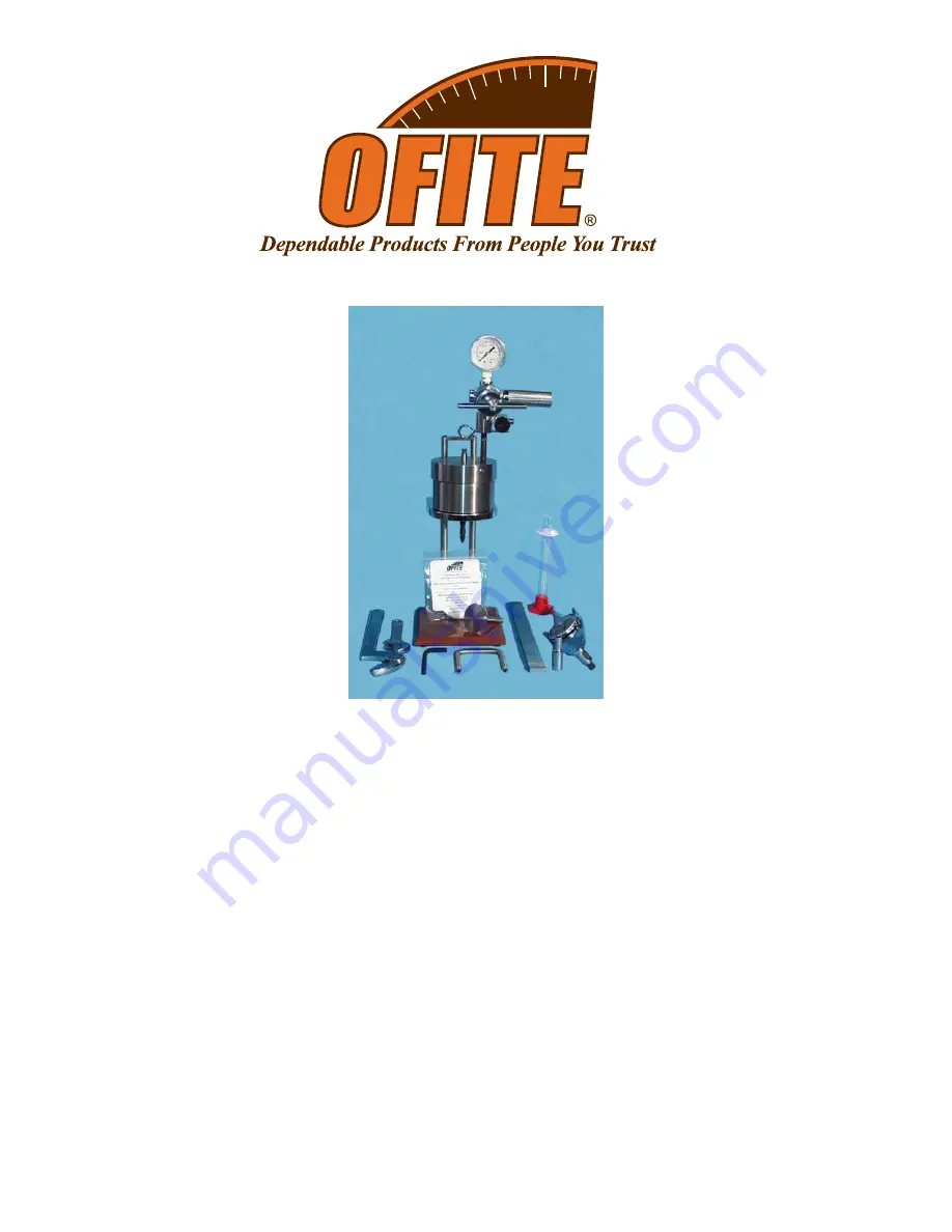
Differential Sticking Tester

Part No. 150-50

Instruction Manual 

Updated 5/29/2009

Ver. 2.0

OFI Testing Equipment, Inc.

11302 Steeplecrest Dr. · Houston, Texas · 77065 · U.S.A.

Tele: 832.320.7300  · Fax: 713.880.9886 · www.ofite.com

©

Copyright OFITE 2011

Summary of Contents for 150-50

Page 1: ...icking Tester Part No 150 50 Instruction Manual Updated 5 29 2009 Ver 2 0 OFI Testing Equipment Inc 11302 Steeplecrest Dr Houston Texas 77065 U S A Tele 832 320 7300 Fax 713 880 9886 www ofite com Copyright OFITE 2011 ...

Page 2: ...Test Procedure 6 Timed Filtration 6 Fixed Cake Thickness 11 Disassembly 12 Theory 13 Example 15 Worksheet 16 Maintenance 17 Diagrams 18 Full Unit 18 Cell Assembly 19 OFITE 11302 Steeplecrest Dr Houston TX 77065 USA Tel 832 320 7300 Fax 713 880 9886 www ofite com 1 ...

Page 3: ...nd how effec tive a given treatment may be can be immediately determined on site The unit is normally pressurized by a CO2 pressuring assembly but any nitrogen source will also work If nitrogen is used the tester apparatus must be fitted with a suitable nitrogen regulator gauges valves and high pressure hoses The standard test uses 477 5 PSI 3 291 kPa applied to a 200 mL stainless steel vessel The...

Page 4: ...nit 143 02 10 CO2 Puncture Head Assembly 143 03 Barrel for CO2 Cartridge 170 08 Regulator 170 20 Manifold Block 170 32 1 8 1 8 NPT Male Needle Valve 171 22 Retainer Pin 171 34 1500 PSI Gauge 2 NPT Bottom 170 13 Test Cell O ring Buna N 170 15 Base 170 16 Valve Stem Qty 2 170 17 Valve Stem O ring Qty 10 170 19 2 6 35 cm Filter Paper Specially Hardened for Filter Presses 170 35 6 Adjustable Wrench 17...

Page 5: ...ulator Repair Kit for 143 00 143 22 Gasket for Puncturing Pin Qty 12 150 51 Locking Mesh Disc Qty 10 150 52 Neoprene Gasket Qty 10 150 53 Plastic Gasket Qty 8 153 16 Glass Graduated Cylinder 25 mL 2 10 mL Qty 2 170 13 Test Cell O ring Buna N Qty 4 170 16 Valve Stem Qty 2 170 17 Valve Stem O ring Qty 20 170 19 2 6 35 cm Filter Paper Specially Hardened for Filter Presses Qty 5 170 23 60 Mesh Screen ...

Page 6: ...ressurization could cause them to explode Before pressuring always check to be sure the regulator is in a closed position by ensuring the T screw is backed out and free turning Insert and puncture the CO2 cartridge by turning the barrel only a quarter turn past the actual puncture point Adjust the regulator to the desired pressure with the regulator T screw With the Differential Sticking Tester ne...

Page 7: ...s 12 5 31 75 cm and simulates a 25 63 5 cm diameter drill casing or col lar The flat torque plate 150 58 is completely flat across the surface The difference between the two is sometimes difficult to see To distinguish between the two place them next to each other on a flat surface The spherical torque plate will rock slightly while the flat torque plate will sit firmly 1 Make sure the unit is cle...

Page 8: ...ed 6 Place the inner cap back into the cell Make sure the o ring seats prop erly beneath the inner cap Refer to the photos on page 8 7 Turn the cell over and secure the inner cap with the two allen screws 8 Tighten the retaining ring securely with the supplied retainer wrench 9 Inspect the o rings on the valve stems and replace any that show signs of wear or damage Screw one of the valve stems int...

Page 9: ...to the test cell body Make sure the o ring is properly seated in the groove in the cell cap 14 Tighten the cell cap using the supplied spanner wrench For additional leverage place the lever arm horizontally between the two support legs Once the cell cap is tightened rotate the cell on the stand until the valve stem hole is oriented away from the stand supports This will pro vide more space for the...

Page 10: ...er the cell and open the lower valve stem by turning it counter clockwise turn 21 Make sure the torque plate is up as far as possible by turning and pulling it upward 22 Open the top valve stem turn to initiate filtration Record the time of the start of the test 23 Continue filtration for 10 minutes or until the desired filtrate volume is collected If the yoke option is being used filter until the...

Page 11: ...P Filter Press back pressure receiver may be substituted for the graduated cylinder while the torque readings are being taken A length of rubber or tygon tubing can also be attached to the valve stem with the outlet end attached to a closed container 28 Measure the torque by rotating the torque plate in either direction with the torque wrench Observe the dial reading 29 Repeat the torque measureme...

Page 12: ...ate touches the filter paper or the locking mesh Now turn the T screw back until the torque plate face is the desired distance from the filter paper One turn of the T screw raises the torque plate 1 32 8 mm 5 Open the top valve stem and record the time as the start of the test 6 Allow the cell to filter until the plate becomes stuck You will know the plate is stuck when you hear an audible click T...

Page 13: ...e of the torque plate 10 Note the diameter of the depression from the torque plate If this diam eter is less than 2 inches or if any cake is adhering to the edge of the torque plate estimate the edge height of the cake from the filter paper If the cake is stuck to the torque plate rather than to the filter paper then the test is invalid Repeat the test using the locking mesh 11 Using the retainer ...

Page 14: ...Fn Normal force on plate Ksc Bulk Sticking Coefficient Kst Stuck Tendency Coefficient a The Sliding Force Fs The Sliding Force Fs is a function of the measured torque Tu This equation should only be used when the radius is 1 and edge effects are not being considered Fs 1 5 Tu b The normal force Fn The Normal Force Fn is determined by multiplying the area by the differential pressure This assumes t...

Page 15: ...ects Ksc Fs Fn 1 5 Tu r πPr2 4 3πrhP 1 5Tu πPr2 r 4 3h For a standard pressure of 477 5 PSI 3 292 kPa and r 1 Ksc 1 5 Tu 1 500 1 4 3h Ksc 001 Tu 1 1 33h The Stuck Tendency Coefficient Kst is equal to the Bulk Sticking Coefficient Ksc multiplied by the variable stuck area Kst Ksc Variable Stuck Area Tu Kst is not valid for the flat plate because the stuck area is either 0 or 3 14 in2 r 1 and not a ...

Page 16: ...1 inch pounds 47 23 kgt cm The drilling fluid sample has an average 0 039 Stuck Tendency Coefficient The pressure is then removed and the cell is carefully opened leaving the torque plate set in the filter cake The torque plate and cake are washed and the torque plate is turned not lifted loose The diameter of the imprint of the torque plate impression smoothed dome area is measured at 1 57 3 95 c...

Page 17: ...SI 3 292 kPa and inch dimensions For cake with 1 radius edge effects considered and a pressure 477 5 PSI 3 292 kPa Ksc 3 For tests using the yoke attachment the cake thickness before sticking should be recorded and the data in 1 2a and 2b above apply OFITE 11302 Steeplecrest Dr Houston TX 77065 USA Tel 832 320 7300 Fax 713 880 9886 www ofite com 16 Average Torque Wrench Reading 001 1 1 33 Cake Hei...

Page 18: ...t or dry sand paper Deeper corrosion pitting may be removed by sand blasting the area of the corrosion If severe corrosion is evident the cell should be replaced 6 A metal to metal pressure tight seal is made between the valve stem and its seat Leaks can occur if either the valve stem or the seat is damaged The conical point of the valve stem should be inspected for damage by removing the stem fro...

Page 19: ...77065 USA Tel 832 320 7300 Fax 713 880 9886 www ofite com 18 Valve Stem 170 16 Retainer Pin 171 22 Valve Stem 170 16 Torque Wrench 150 54 Socket 150 57 Test Cell O ring 150 56 Torque Plate 150 58 150 59 Cell Assembly See Page 19 CO2 Pressurization Unit 170 04 ...

Page 20: ...lecrest Dr Houston TX 77065 USA Tel 832 320 7300 Fax 713 880 9886 www ofite com 19 Retainer Wrench 150 55 Retaining Ring Plastic Gasket 150 53 Neoprene Gasket 150 52 Locking Mesh Disk 150 51 Filter Paper 170 19 Inner Cap with Screen 150 50 5 ...

Reviews: