


170
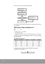
Auto tuning is done in the following sequence.
If it is set too low compared to the load, the calculated inertia ratio can
be inaccurate.
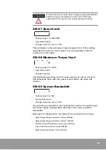
SEt-59 Input Signal Assignment 1
•
Setting range: 0 x 0 to 0 x 9999
•
User Default: 0 x 4321
•
Change while the servo is OFF, and turn off the power and turn it back on
The input signals should be assigned to the CN1 connector’s input pins
from DI#1 to DI#8.
For instance, put 7 in the fourth digit of SEt-59 to allocate the
/P-CON signal to the DI#7 pin.
Input Signal Allocation Table
Parameter
Fourth Digit
Third Digit
Second Digit
First Digit
SEt-59
/P-CON
N-OT
P-OT
/SV-ON
SEt-60
/C-SEL
/P-TL
/N-TL
/A-RST
SEt-61
/C-SP3
/C-SP2
/C-SP1
/C-DIR
SEt-62
/A-TL
/G-SEL
/INHIB
/Z-CLP
SEt-63
/P-CLR
/R-ENC
/EMG
/ABS-DT
Summary of Contents for CSDP Plus
Page 1: ...Maximum Value for OEMs SM CSDP Plus Servo Drive User Manual...
Page 16: ...18...
Page 30: ...32 Higher Control Connector CN1 Circuit Diagram...
Page 33: ...35 Compact Absolute Encoder Wiring Serial Encoder Wiring...
Page 38: ...40...
Page 120: ...122...
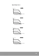
Page 179: ...181 Speed Torque Curve...
Page 180: ...182...
Page 183: ...185 Speed Torque Curve...
Page 184: ...186...
Page 187: ...189...
Page 190: ...192 Speed Torque Curve...
Page 193: ...195...
Page 196: ...198...
Page 201: ...203...
Page 204: ...206...
Page 207: ...209...
Page 210: ...212...
Page 215: ...217...
Page 230: ...232...
Page 252: ...254...
Page 253: ......


