


117
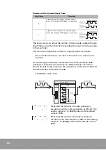
Even when the motor is revolving at a completely normal speed,
jittering of about 33
µ
s can be generated at the encoder output pulse
depending on the revolution speed.
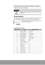
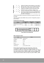
Analog Monitor
The servo drive can display the analog monitor signals with which the
user can check the actual control status through an oscilloscope.
Set the scale units of the analog monitor channel 1
and channel 2 at
SEt-78.
ATTENTION
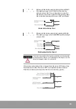
The servo drive cannot send more pulses than the number of
input pulses from the encoder to the controller. Therefore, the
numerator should always be the same as or smaller than the
denominator.
Analog Monitor Output Type
Chosen Number
Types
Setting Range (1V)
0
Speed Command
1 to 500 RPM
1
Torque Command
1 to 30%
2
Position Command
1 to 5000 pulse
3
Speed Feedback
1 to 500 RPM
4
Torque Feedback
1 to 30%
5
Position Feedback
1 to 5000 pulse
6
Position Error
1 to 2500 pulse
7
Speed Error
RPM
8
DC-link Voltage
V
9
Θ
(theta_cnt) Electrical
Angle
°
10
Pulse Command
Frequency
kHz
11
Inertia Ratio
%
12
Q Axis Current
A
13
D Axis Current
A
14
U Phase Current
A
15
V Phase Current
A
16
W Phase Current
A
Summary of Contents for CSDP Plus
Page 1: ...Maximum Value for OEMs SM CSDP Plus Servo Drive User Manual...
Page 16: ...18...
Page 30: ...32 Higher Control Connector CN1 Circuit Diagram...
Page 33: ...35 Compact Absolute Encoder Wiring Serial Encoder Wiring...
Page 38: ...40...
Page 120: ...122...
Page 179: ...181 Speed Torque Curve...
Page 180: ...182...
Page 183: ...185 Speed Torque Curve...
Page 184: ...186...
Page 187: ...189...
Page 190: ...192 Speed Torque Curve...
Page 193: ...195...
Page 196: ...198...
Page 201: ...203...
Page 204: ...206...
Page 207: ...209...
Page 210: ...212...
Page 215: ...217...
Page 230: ...232...
Page 252: ...254...
Page 253: ......


