background image

404

TSM Océ 3121

Dis-/assembly

3 Vertical Path Assembly

1

Remove the following:

Pick-up assembly 

Pick-up drive unit 

2

Remove the two rolls, and disconnect the connector; then, remove the multi-
feeder assembly.

3

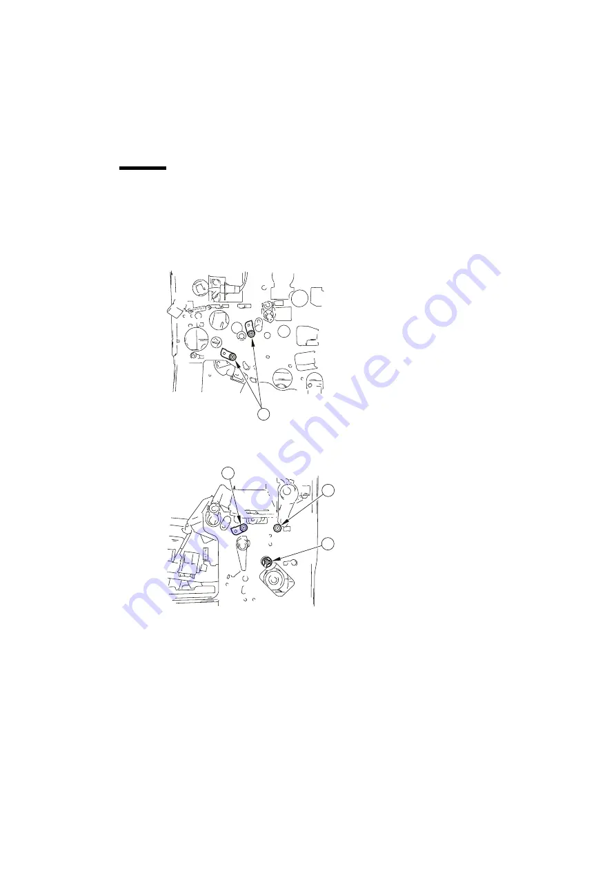
Remove the two screws (1) from behind the machine.

4

Release the feeding lever, and remove the three screws to remove the feeding 
lever and the feeding assembly locking assembly.

5

Remove the screw (2), grounding screw (3), and E-ring (4).

1

2

3

4

Summary of Contents for 3121

Page 1: ...Technical Service Manual Oc 3121 3122 Oc Oc Oc Oc 3121 3122...

Page 2: ...R 02 CHARGING 04 EXPOSURE 05 DEVELOPING 06 TRANSFER 07 CLEANING 08 IMAGE PROCESSING 10 RDF 11 DIGITAL DOCUMENT HANDLING 12 PAPER 13 SPECIALITY INPUT 16 DUPLEX 17 FIXING 19 DELIVERY 21 SORTER 22 POWER...

Page 3: ...s 160 Others 05 Developing 161 Developing roller 162 Developing clutch CL4 163 Toner agglomeration 164 Toner level sensor TS1 165 Toner bias 198 Mechanical connections 199 Electrical connections 200 O...

Page 4: ...ed arm 482 Speciality pick up roller 483 Speciality roller clutch CL2 518 Mechanical connections 519 Electrical connections 520 Others 16 Duplex 601 Inlet 602 Lower feeding inlet assy 620 Lower paper...

Page 5: ...arrival 962 Customer 963 Speciality incorrectly posi tioned 964 Original incorrectly posi tioned 965 Paper jam incorrectly removed 966 Toner not refilled 968 Others 971 Environment 972 Relative humidi...

Page 6: ...Technical Service Manual Oc 3121 3122 Oc Oc Oc Oc INSTALLATION...

Page 7: ...1 2 Unpacking and installation 3 3 Relocating the Machine 24 4 Installing the Control Card V 25 5 Installation of the Cassette unit 29 6 RDF Installation procedure 32 7 Sorter installation 36 8 The 3...

Page 8: ...iers refrigerators near to sources of fire or dust or ammonia gas places subject to direct sunshine 4 Further requirements are The site must be well ventilated A level floor so that all feet of the ma...

Page 9: ...2 TSM Oc 3121 Installation 170 cm min 180 cm min 6 5 cm 70 cm min 210 cm min 6 5 cm 170 cm min 200 cm min 6 5 cm...

Page 10: ...the plastic covers If necessary unpack the pedestal 2 Holding the copier by the grips place the copier on the pedestal this is work for two people 3 Open the cardboard box and remove the contents Chec...

Page 11: ...lever releasing the feeding unit 8 Turn the lever to the left releasing the developing unit 9 Loosen the screw releasing the dummy drum Keep the removed screw It is to secure the OPC unit 10 Pull the...

Page 12: ...r cartridge sev eral times 3 Place the toner cartridge on the developing unit Push the cartridge down releasing the grip The cartridge will be held in place on the developing unit 4 While holding the...

Page 13: ...black cover back into the developing unit The toner cartridge will be released 7 Remove the toner cartridge 8 Push in the developing unit until it stops 9 Turn the locking lever in the direction of t...

Page 14: ...1 Insert the brush into the release opening locking the fuser unit 2 Insert the dummy actuator in the door switch 3 Connect the mains supply cable 4 Switch ON Separation static eliminator cleaning bru...

Page 15: ...ice 3 Press FUNCTION 4 Then press OK 4 Press to turn pages to the Toner Stirring screen 5 Press START Then press OK The stirring of the toner will start Install the output tray Toner stir screen The s...

Page 16: ...ss and clean it with lint free paper Then refit the glass 5 Unpack the OPC unit Remove the two spacers from between the rollers 120 V Do not remove the drum cover Grip the centre of the OPC unit when...

Page 17: ...the OPC drum unit slowly along the rail 120V model Do not remove the drum cover 7 Secure the OPC unit using the screw that was previously removed No Adjustments Remarks Rail Rail Drum unit Drum unit...

Page 18: ...nt cover of the drum unit 9 Turn the lever locking the developing unit in place Lock the feeding unit in place No Adjustments Remarks date date Datum counter compteur Z hler compteur Z hler notes note...

Page 19: ...selector switch select A B or Inch configuration Each cassette has its own switch Set all switches according to requirements 3 Fix the appropriate label to the rotary switch the recess in the label s...

Page 20: ...Installation 13 4 Holding the lever of the width guide and the length guide slide the guides to suit the index of the appro priate paper size 5 Set the paper size dial to the appropriate paper size No...

Page 21: ...he cassette size label as shown to identify the size of the paper Note Sizes A3 and 11 x 17 cannot be handled by the cassettes 3 and 5 As counted from the top 7 Place copy paper in the cas sette No Ad...

Page 22: ...Select Store and Yes Press Done twice Now the three symbols are visible and in the display the text photo button is selected 4 Press the service switch and press the key twice A will be displayed on t...

Page 23: ...the telephone socket No Adjustments Remarks 1 Turn ON the main power switch 2 Press the User Mode key and press FAX spec settings on the screen that has appeared 3 Press Basic Registration The setting...

Page 24: ...m causing it to highlight Enter the appropriate value using the keypad Then press OK 5 If you wish to adjust NL go to step 3 of NL adjustment If you are not adjusting NL press Cancel and press Reset t...

Page 25: ...ove the brush and the door switch actuator Then close the front door 2 Perform test print to make sure that the images are nor mal Taking Test prints Press FAX to select the FAX screen Press Special f...

Page 26: ...the lower right cover as shown Then slide out the upper and lower cassettes and fit and tighten a screw 3 Using test chart 1 make copies to check the images Optimum Images Text The white background is...

Page 27: ...a thin pin press the service switch 3 Press twice 4 Press FUNCTION 4 on the LCD causing it to high light Then press OK 5 Press to turn pages to the Shading screen 6 Press AUTO SHADING START on the LC...

Page 28: ...atic Adjust ment screen 7 Close the front cover as far as possible and press PD PRINT on the screen causing it to high light Then press the copy but ton The copier will generate a test pattern This wi...

Page 29: ...PLING check that the set tings under A B and D are as specified Insert PD 20 A 50 200PWM 40 B 40 0 D 8 20 A 60 600PWM 70 B 20 0 D 8 If the settings are correct press SET causing it to highlight Then p...

Page 30: ...Then make copies at density set ting 5 in text mode in test and photo mode and in photo mode Try all the cassettes and the speci ality tray Optimum Images For text mode the background must remain whi...

Page 31: ...ove the OPC Put the OPC unit in a separate box for transport 2 Fix the scanner in place 3 Tape the charging assemblies and the feeding unit releasing lever in place to prevent dis placement by vibrati...

Page 32: ...unit The lever of the feeding unit The knob of the registration roller The upper cassette 2 Remove the inside cover 5 screws see chapter Miscellaneous 3 Remove the following so that the control panel...

Page 33: ...e display of the Control Card V Installing the Control Card 1 Position the Control Card 1 on the control panel using four screws 2 Note Slide a card in and out and fix the Control Card V when a card c...

Page 34: ...the Control Card V taking care not to trap the wires 3 Fit the control panel to the copier 4 Fit the fuser control PBA 5 At this time be sure to fix the grounding wire 6 of the Control Card V in place...

Page 35: ...he 4P connectors 10 and 11 8 Position the plastic 12 in the hole in the control panel 9 Remove the backing sheet from the face plate 10 Attach the face plate 13 to the control panel 11 Attach the memo...

Page 36: ...te unit 1 unit Do not lift label 1pc Label set 2 or 4 sets Preparations If the lower right cover is fitted to the copier remove it 1 Disconnect the mains supply cable 2 Slide out the upper cassette an...

Page 37: ...remove the cover Installation 1 Open the right hand panel 2 Open the vertical transport unit 3 Holding the copier by its grips carefully place the copier on the pedestal 4 Close the vertical transpor...

Page 38: ...from the cassette feeding unit to the copier 6 Continue with the work for each cassette as described at Installing the Cas settes on page 12 7 Attach the DO NOT LIFT label as shown 8 Perform Adjusting...

Page 39: ...121 Installation 6 RDF Installation procedure Unpacking the machine RDF 1 unit Stepped screw 1 pc Delivery tray 1 pc Tray hinge 1 pc Hinge cover 1 pc Screw M4x30 1 pc Screw M3x4 2 pcs Guide base 1 pc...

Page 40: ...come with a washer to protect against static electricity Ensure that these are used 1 Lift the platen cover and remove it from the copier 2 Remove the two screws and remove the platen retainer from t...

Page 41: ...F into the holes in the copier Ensuring that the bolts of the supports are at the bottom of the holes Close the RDF 5 Remove the connector cover 6 Connect the RDF connector Warning Ensure that the mai...

Page 42: ...not touch the stamp face Immediately rinse your hands if you touch the ink Checks after Installation After installation adjust the following the height of the RDF see 10 adjustment 1 the document posi...

Page 43: ...position label A 1 pc 5 Stapling position label B 1 pc 6 Tray label 1 pc 7 Stepped screw 6 x 11 2 pcs 8 Cable bushing 1 pc 9 Latch plate 1 pc 10 Harness band 1 pc 11 Guide plate 1 pc 12 Delivery guide...

Page 44: ...and keep the sorter upright 2 Remove the two screws and two butterfly screws Then remove the metal fix ing A from the sorter Remove the screw and remove the metal fixing B 3 Remove the taping and cush...

Page 45: ...38 TSM Oc 3121 Installation Installation 1 Mount the delivery guide 2 Install the latch plate with the two stepped screws 6 dia x 11 Delivery guide Stepped screws Mounting hole Cushioning material...

Page 46: ...ologies B V ed 1 Installation 39 3 Remove the hinge cover of the copier s left cover using a screwdriver 4 Fix the reinforcement plate in place to the copier with two screws black M4 x 6 Hinge cover R...

Page 47: ...wo cut offs on the copier s left side Warning Be sure to support the bottom of the sorter when lifting the sorter Do not hold the stapler cover Note To facilitate the work put cushioning material as s...

Page 48: ...x the sorter in place with two stepped screws 6 dia x 27 5 8 Remove the connector cover from the rear of the copier Warning Be sure that the mains cable is disconnected 9 Connect the sorter s cable to...

Page 49: ...ter from the copier 2 Open the sorter s right cover and remove the rear right cover 4 screws while detaching the solenoid cable 3 Check to make sure that bit 4 of the DIP switch SW1 on the tray contro...

Page 50: ...idential 1998 Oc Technologies B V ed 1 Installation 43 Installing the paper on tray indicator 1 Attach the cable bushing 2 Insert the cable into the hole Cable bushing Cable bushing Magnet plate Indic...

Page 51: ...two hold it in place with a harness band Then keep the cable in place to the machine using the cable retainer 5 Attach the guide plate 6 Install the rear right cover and close the right cover Then se...

Page 52: ...the labels 1 Attach the label A to the rear of the platen 2 Attach the label B so that the leftmost illustration on the Warning label on the DF is hidden 3 Attach the appropriate tray label to the si...

Page 53: ...er stapling check that the Add Staple indicator has started to flash If it is not flashing adjust the detection level set for staples as instructed in the TSM 5 Supply the stapler with staples instruc...

Page 54: ...very unit Unpacking 1 Height adjusting plate 1 pc 2 Interlock retaining plate 2 1 pc 3 Delivery unit 1 pc 4 Tray sticker 1 pc 5 External cover 1 pc 6 Tray 2 pcs 7 Edge saddle 1 pc 8 Hinge 1 pc 9 Stop...

Page 55: ...unit 1 Switch off the machine and disconnect the mains supply cable 2 Open the front cover 3 Open the delivery unit and remove the connector cover 1 The cover is hooked in place use a finger to snap...

Page 56: ...and shift the lower cover to remove 6 Remove the hinge cover 1 with a small flat blade screwdriver 7 Disconnect the connector of the delivery unit 8 Open the delivery unit and remove the wire 1 from t...

Page 57: ...n the right side Installing the delivery unit to the 3 tray delivery unit 1 Remove the bushing and pull out the fixing shaft 1 2 Remove the lower delivery guide 3 4 screws 2 3 While paying attention t...

Page 58: ...r delivery guide lever wire and interlock retaining plate 1 will not be used 6 Place the 3 tray delivery unit 1 on its side so that the tray side is at the bottom 7 Install the delivery unit to the 3...

Page 59: ...ge saddle and connect it to the connector 8 of the 3 tray delivery unit 11 Install the hinge 1 with six screws 12 Install the height adjusting plate 1 with a screw 13 Check to make sure that the hole...

Page 60: ...the hinge pins 1 of the hinge At this time make sure that you set the 3 tray unit on the bottom shaft and then the top shaft Warning You will not be able to install the 3 tray unit securely if the ope...

Page 61: ...de of each tray 3 Install the spacer 4 with one screw Checking the operation 1 Switch off and on the main power to check that the 3 tray delivery unit shifts correctly 2 Perform a copy job while testi...

Page 62: ...e as shown in the figure and re move the CORE PBA from the Base Unit Be sure to use the new cable tie when refitting the CORE PBA 1 Ensure that the copier has been properly installed 2 Ensure that the...

Page 63: ...aker holder 2 Fit the speaker and the speaker shell in the expansion unit Fit the notches on the speaker shell into the holes in the expansion unit Turn it to lock Speaker Speakerhol der Speaker shell...

Page 64: ...Switch Configuration The NCU for France has no switches NCU Switch Settings Modular unit 1 Fit the modular unit in the Expansion Unit 1 screw 2 If the CORE IP PBA has not yet been installed install i...

Page 65: ...aight This can best be seen from the CORE IP PBA side Core Position the core in the Base Unit Using the cable tie seccure the core in the appropriate manner 1 Type 1 with a Square Hole 4 holes Scr ew...

Page 66: ...rs J2 J3 and J4 on the NCU PBA of the FAX PBA Europe except France When positioning the core round take care that bits 1 through 3 of the switch on the NCU will not interfere with the core CO RE Ti e...

Page 67: ...nd check to make sure that it is secure 2 Connect the cable for the speaker to J2 as shown Then lead the harnesses for the earth cable and the modular unit through the square bush Lead behind Ql FAX B...

Page 68: ...or the modular unit as shown Insert the FAX PBA in the Expansion Kit 4 Free the harness coming from the copier from the edge saddle Lock suppor t ARG cabl e CO RE cube Har ness ofm odul aruni t Harnes...

Page 69: ...Before fitting the front cover Ensure that all bits of the switch as shown in the figure are shifted to the top positions 3 pi n connect or sm al l 5 pi n connect or l ar ge Edge saddl e CO RE cube H...

Page 70: ...shown 8 Shift the slide switch SW2 from OFF to 3 9 Fit the cover to the expansion unit Be careful not to trap any wires Screw washer 10 Remove the jack cover from the rear panel of the copier 11 Fit...

Page 71: ...ed as resolution Ultra Fine Mode may be selected Slot B Used for image memory 9Mb or 3Mb may be installed increases memory for transmission reception images Installation 1 Turn OFF SW2 on the Fax PBA...

Page 72: ...Technical Service Manual Oc 3121 3122 Oc Oc Oc Oc IMAGE QUALITY...

Page 73: ...check 1 2 Image adjustment basic procedure 3 3 Check and adjustment of the image registration 4 4 Trouble shooting image faults 6 5 Isolating a PBA FAX image fault 21 6 Shading for service 22 7 Automa...

Page 74: ...a reddish background tend to have a poor contrast 3 Check the contrast of the documents diazo documents or transparencies can produce vague copies documents with pencil drawings or pencil text tend t...

Page 75: ...ms 1 Condensation in the document exposure system or the laser exposure system glass mirror lens causes light or dark images 2 Condensation in the charging system can cause leakage 3 Condensation in t...

Page 76: ...Confidential 1998 Oc Technologies B V ed 1 Image quality 3 2 Image adjustment basic procedure...

Page 77: ...feeding assembly 1 The Image Read Position To adjust the CCD reading start position in the sub scanning direction SDS 3 ADJUST 04 V ADJ A higher setting delays the registration ON timing To adjust th...

Page 78: ...werfeeding assemely 2nd side of two sided overlay copies Rear front adjustment for images on paper from the lower feeding assembly Check to make sure that the printing position of the image on the sec...

Page 79: ...s too light Yes Carry out AE adjustment In the case of image quality priority mode increase the setting 3 AD JUST AE_DARK In the case of speed priority mode increase the setting under 3 AD JUST ABC_TB...

Page 80: ...fer roller Yes Replace the transfer charging roller 6 Check the spring for the transfer roller undam aged correct tension No Correct the position of the spring or replace the spring Paper Transfer fau...

Page 81: ...eveloping unit Toner detection Development fault 10 Does the developing unit contain toner No Check the toner sensor Check the connector and the harness for electrical continuity OPC unit 11 Replace t...

Page 82: ...he transfer unit High voltage cable Transfer unit Transfer fault 5 Is there electrical conti nuity between the power supply PBA and the transfer roller No Replace the high volt age cable Check the tra...

Page 83: ...esulting image is satisfactory keep the set ting to 1 as a temporary remedy However be sure to take proper action as there may be a problem on the image processor PBA or the DC control PBA Developing...

Page 84: ...he OPC unit Light intrusion No Check whether the OPC is being subjected to exposure from an out side source Cause Step Checks Y N Action Laser exposure system 1 Make a test copy using 4 L TEST2 in ser...

Page 85: ...oner on the develop ing roller No Check the edge of the doctor blade If there is no toner in the developing assembly refer to The ADD TONER message is not displayed Fusing unit 4 Are there scratches o...

Page 86: ...Is the problem repeated at intervals of approxi mately 94 mm Yes Clean the OPC If there are scratches replace the OPC unit Paper 4 Using an alternative copy paper is the image darker Yes The paper may...

Page 87: ...n roller 3 Is the problem repeated at intervals of approxi mately 50 mm Yes Clean the registration roller Clean the transfer guide Check the developing unit for leakage of ton er OPC cleaning unit 4 I...

Page 88: ...user to use this cassette for thick paper 2 Is a recommended type of paper being used No Make a test run using recommended paper If the results are satisfac tory advise the user to use recommended pa...

Page 89: ...k the lower fuser roller Yes Check and clean Registration roller The pick up roller and the feeding guide Cause Step Checks Y N Action Scanner cable 1 Is the cable twisted or frayed on the pulley when...

Page 90: ...in direct mode Has the location of the problem changed Yes Check the scanning sys tem OPC drive OPC unit No Check the feeding system Cause Step Checks Y N Action 1 Is a printed photo with raster patte...

Page 91: ...a leakage of charge from the transfer roller Yes Check the transfer unit High voltage cable for the transfer 7 Is there an open circuit or poor contact on the trans fer HT cable The cable leads from t...

Page 92: ...5 3 on the power supply PBA and the charging roller No Reconnect 3 Execute test printing using 4 L TEST1 7 In service mode Is the image cor rect on the OPC No Go to step 5 DC control PBA 4 Connect the...

Page 93: ...20 TSM Oc 3121 Image quality Isolating a PBA printer image fault...

Page 94: ...Confidential 1998 Oc Technologies B V ed 1 Image quality 21 5 Isolating a PBA FAX image fault...

Page 95: ...e should be used in the following situations When replacing the image processor PBA After executing 4 RAM INIT Before executing 4 COPY AUTO DENSITY CORRECTION After replacing the power supply PBA Afte...

Page 96: ...ayed 5 Press FUNCTION 4 It will highlight Then press OK 6 Press the Page key to bring up the shading screen 3rd screen 7 Press AUTO SHADING on the LCD causing it to highlight Then press OK Shading Aut...

Page 97: ...ity This mode is executed to correct the following Laser characteristics Developing bias This mode should be used in the following situations After replacing the laser unit After replacing the power s...

Page 98: ...e platen cover open make two totally black copies 10 2 Check that is displayed on the LCD Then press once 11 Press FUNCTION 4 causing it to highlight Then press OK 12 Press the Page key to bring up th...

Page 99: ...or rect adjustment will not be possible Place the test pattern face down on the platen If the pattern copy is positioned wrongly the image will be much lighter 18 Press DENSITY SAMPLING causing it to...

Page 100: ...steps starting with step 9 22 When 200 PWM density automatic adjustment is finished execute 600 PWM density automatic adjustment Follow the same steps starting with step 9 23 Press Reset twice ending...

Page 101: ...cycle Shading for R D and factory Execute the R D mode in the following situations After replace the exposure reference strip After replacing the scanner lamp After replacing the DC control PBA 1 Open...

Page 102: ...ess OK Shading Auto Correction will be executed 9 A beep will sound while the lamp is adjusted LAMP LEVEL will be dis played Press OK when the beep stops If no beep is heard remove the rear cover and...

Page 103: ...r ABC_TBL will make the image lighter value 1 9 default 3 The adjustment will modify the density correction curve Priority on image quality mode 1 AE_SLOP For priority on image quality an AE table is...

Page 104: ...y hi st ogr am Dar k bl ack Li ght whi t e Si gnall evel Degr ee Text Backgr ound AE t abl e I nput O ut put Li ght whi t e Dar k bl ack Bl ack W hi t e I nput O ut put Li ght whi t e Dar k bl ack Bl...

Page 105: ...Technical Service Manual Oc 3121 3122 Oc Oc Oc Oc TROUBLE SHOOTING...

Page 106: ...ot realign 16 6 E010 Main motor fails to lock 17 7 E030 The total counter fails 17 8 E031 The fax counter fails 17 9 E032 The copy data controller is faulty 18 10 E051 The home detection of the horizo...

Page 107: ...C communication chip on the image processor PBA has a fault 36 41 E711 E712 E713 E716 IPC communication error 36 42 E717 Error in the communication with the copy data controller 36 43 E803 24 V output...

Page 108: ...Confidential 2000 Oc Technologies B V ed 2 Trouble shooting RDF Self Diagnosis FAX related error codes...

Page 109: ...ED on the composite power supply PBA Also the RDF and the 12 bin sorter have their own self diagnosis system which are able to generate error codes and alarm codes The error codes are displayed on the...

Page 110: ...mistor TH2 detects less than 90 C for 200 ms 4 sec after volt age has been applied to the heater E001 The fixing temperature rises abnor mally Thermistor TH1 TH2 short circuit DC control PBA faulty Th...

Page 111: ...control PBA faulty The main thermistor TH1 detects less than 150 C for 200 ms after it has detected 150 C The sub thermistor TH2 detects less than 150 C for 200 ms after it has de tected 150 C E007 Th...

Page 112: ...omposite power supply PBA DC control PBA Wiring short circuit open circuit The difference between the high volt age control signal and the actual high voltage output is more than a specific value Ther...

Page 113: ...th the control panel Control panel CPU Image processor PBA An error has been detected in the com munication between the CPU on the control panel and the image processor PBA E261 There is an error in t...

Page 114: ...ansmit pulses within 4 seconds after the motor drive signal BFMD has been gener ated E515 12 bin output unit The tray feeding motor M6 fails to rotate The clock sensor PI6 of the tray feeding motor ha...

Page 115: ...lt The fax unit has poor connection An error is detected when writing to the chip while receiving a fax message E675 Tolerance in power supply of the expansion B2 kit Bad communication between IP boar...

Page 116: ...y PBA Both ends of the fluorescent lamp are blackened because of deteri oration Incorrect output voltage 24VU or 24VR of the composite power supply PBA E901 Cassette unit Pedestal motor M20 faulty Ped...

Page 117: ...te ERROR in service mode 4 Note that E007 01 in service mode will be indicated as E007 omitting the last two digits under ERR of DISPLAY in service mode 1 After the film has returned to normal positio...

Page 118: ...e Description 0 5 seconds ON 0 5 seconds OFF Normal The composite power supply PBA is functioning in a normal manner 2 seconds ON 2 seconds OFF Excess cur rent An excess current has been detected Or a...

Page 119: ...n of these codes see the SDS description chapter 1 DISPLAY 03 6 seconds ON 6 seconds OFF Low voltage control error during copy ing Unacceptable difference between the 24VR output and the actual contro...

Page 120: ...etects a jam it will turn OFF the main motor and indicate a jam message on the control panel Sensor Signal Connection PS4 Sensor for the speciality tray MFPD J113 A11 PS5 Sensor for the pre registrati...

Page 121: ...per Note A jam will be signalled in any of the following occur during copying the front door is opened the right door is opened the output door is opened or the cassette is withdrawn Record of jams T...

Page 122: ...t the fixing assembly to cool then disconnect J50 and measure the resistance of the thermis tor Is the reading as fol lows J501 2 yellow line about 1388 kohm J503 4 white line about 3636 kohm No Repla...

Page 123: ...place the DC control PBA Cause Step Checks Yes No Action 1 Clear the error using ERROR in serv ice mode 4 Is any of the following correct after the machine has booted The fixing heater fails to switch...

Page 124: ...Yes Replace the fuser unit Releasing lever 5 Is the releasing lever faulty Yes Replace the fuser unit Detect lever 6 Is the tension spring of the detect lever in good condition Also does it move smoot...

Page 125: ...river normal J150 1 24 V J150 2 0 V No Check the wiring from J204 3 24 V J204 4 0 V on the composite power supply PBA to the main motor if normal see DC power is absent Main motor 4 Replace the main m...

Page 126: ...l PBA Cause Step Checks Yes N o Action 1 Is the registration sensor PS14 function ing normally Procedure Open the right door and insert copy paper into the pick up feeding assembly through the lower f...

Page 127: ...er charging assem bly transfer charging roller 3 Check the connections of the transfer unit and the transfer roller Yes Replace the transfer unit or the transfer roller Primary charging roller 4 Remov...

Page 128: ...onnect J518 Yes Check the connector J518 on the image processor PBA If cor rect go to 2 J5041 2 Is J5041 connected to the BD PBA No Reconnect J504 Yes Check the connector J504 on the image processor P...

Page 129: ...on the laser scan ner driver PBA to the connector J204 5 6 on the composite power supply PBA Laser scan ner drive PBA laser scanner unit Yes Try replacing the follow ing items Laser scanner drive PBA...

Page 130: ...nector J209 on the composite power supply PBA normal No Reconnect composite power sup ply PBA and the DC con trol PBA Yes Try replacing the follow ing items DC control PBA composite power sup ply PBA...

Page 131: ...ow intensity DC control PBA 2 Replace the DC control PBA Is the problem corrected Yes Replace the DC control PBA composite power sup ply PBA No Check the wiring of the DC controller PBA and the compos...

Page 132: ...No Connect the connector properly Theoperating panel 3 Replace the control panel Is the problem corrected Yes End Image proc essor PBA No Replace the image proc essor PBA Cause Step Checks Yes No Act...

Page 133: ...ensor Is the problem solved Yes End Intensity sen sor 4 Replace the intensity sensor Is the problem solved Yes End DC control PBA No Replace the DC control PBA Cause Step Checks Y N Action 1 Turn off...

Page 134: ...Start key is pressed Yes Check the wiring from the pick up motor M1 to the RDF controller if normal replace the pick up motor M1 No Replace the RDF control ler PBA Cause Step Checks Y N Action Belt m...

Page 135: ...feeding motor M2 to the RDF controller PBA if normal replace the feeding motor M2 No Replace the RDF control ler PBA Cause Step Checks Y N Action Original tray paper sensor S1 Registration sen sor S3...

Page 136: ...py data controller and the copier No Connect the cable cor rectly Multi tray commu nication mode 1 Is the mode set correctly Use the DIP switch on the tray control PBA to set the mode No Reset the mod...

Page 137: ...when the manual staple button is pressed To stop press the button again No Check the cables to motor M2 If undamaged replace the motor M2 Tray control PBA 3 Disconnect J5 from the tray control PBA Che...

Page 138: ...o to step 3 Tray drive motor M6 2 Disconnect J10 from the tray con trol PBA Check the resistance between J10 1 and J10 2 cable side Correct is approximately 100 Ohm No Check the wiring to the tray dri...

Page 139: ...tray is at the front and 5 V when the tray is at the rear Yes Check the wiring to the tray position sensor PI12 If undamaged replace the sensor Tray control PBA No Replace the tray control PBA Cause S...

Page 140: ...and J7 11 on the harness side about 20 ohm No Replace motor M3 4 Connect the to J7 11 and the to J7 10 on the tray control PBA Does the voltage change to approximately 24 V Yes Replace motor M3 Stapl...

Page 141: ...eased No Replace the home sensor MS1 Lead cam home position sensor PI1 5 Connect to the tray controller PBA to J8 6 and to J8 5 Does the meter reading alter nate between 5 V and 0 V when the lead cam...

Page 142: ...BA The correct reading is 24V imme diately after switching the machine ON No Replace the sensor for the tray position Cause Step Checks Yes No Action 1 Turn off and then on the main power YES End PBA...

Page 143: ...Correct the connection At this time check the pins for deformation Fax PBA NO Replace the fax PBA Cause Step Checks Yes No Action Power supply from B2 kit See Modification bulletin survey on page 6 1...

Page 144: ...ted YES End Image proces sor PBA NO Check that the image processor PBA is free of dust or foreign matter then replace the image processor PBA Cause Step Checks Yes No Action 1 Switch OFF then ON Is th...

Page 145: ...e lamp DC control PBA 3 Replace the DC control PBA Is the problem corrected Yes End Composite Power sup ply PBA No Replace the composite Power supply PBA Cause Step Checks Yes No Action Error code 1 I...

Page 146: ...ter probes to both terminals fastons of the main power switch Is the resistance 0 ohm when the switch is turned ON and ohm when the switch is turned OFF No Replace the main ON OFF switch Noise filter...

Page 147: ...nectors Com posite Power Supply PBA J204 J211 J213 J214 J215 ACC Power Supply J134 J142 Is the output voltage of each terminal Table nor mal No Turn OFF the power switch connect one of the disconnecte...

Page 148: ...utput J204 1 2 3 4 5 6 7 8 9 10 24VU 0Vu 24VU 0Vu 24VU 0Vu 24VU 0Vu 24VU 0Vu J213 1 2 3 4 5 6 15V 15V 15V 12V 12V 12V J214 1 2 3 15V 0V 12V J211 1 2 3 4 5 6 7 8 9 10 5V 0V 5V 0V 5V 0V 5V 0V 5V 0V J215...

Page 149: ...s B V ed 2 Trouble shooting 41 Position of the OPC 2 Reposition the OPC unit Is the problem corrected Yes End OPC drive No Remove the drum drive assembly and correct or replace the parts as nec essary...

Page 150: ...ick up motor Is the problem solved Yes End Fuse F1601 on the pick up PBA No Check the fuse F1601 on the pick up PBA If it is intact go to the next step DC control PBA 5 Is the leading edge of the pape...

Page 151: ...eder holding plate releasing solenoid SL3 3 Connect the to J14 B12 and the to J14 B13 on the DC control PBA Does the meter reading change from 0V to approximately 24 V when the copy button is pressed...

Page 152: ...mes into contact with the scanner Connector poor con tact 3 Check the wiring connection from the connector J116 on the DC controller PBA to the scanner motor Is it normal No Correct it Scanner motor M...

Page 153: ...ion of the relay connectors J20 and J95 nor mal Further is the connec tion of the connector J802 on the composite power supply PBA normal No Reconnect DC control PBA 4 Replace the DC control PBA Is th...

Page 154: ...voltage of the follow ing connectors on the DC con troller PBA change from 0 V to 24 V and then to 0 V after copy paper is discharged Total copy counter CNT1 J107 B3 J107 B4 Printer counter CNT2 J107...

Page 155: ...service mode 1 JAM Yes Remove all paper Sensor 2 Inspect the sensor identified by the jam code 1 No Replace the sensor DC control PBA Yes Replace the DC control PBA Cause Step Checks Yes No Action Sti...

Page 156: ...Do all the installed cassettes contain paper No Add paper The fax error indication lamp flashes if all cas settes contain paper Advise the operator Fax 2 Is the fax reception normal No Check the conne...

Page 157: ...and this error is detected if the communication is interrupted for 5 seconds or more Pick upmotorM1 fails to rotate Pick up sensor S5 faulty A vane is attached to the shaft of the pick up motor M1 The...

Page 158: ...ain cause Action The document has jammed while being fed The size or the thickness of the document is outside the specifications The internal mechanism has a fault Remove the document and restart Make...

Page 159: ...s too long The other machine does not respond The communication mode e g G2 G3 of the other machine is incorrect mismatch The other machine malfunctions because of an echo during transmission The mach...

Page 160: ...her machine is disconnected or switched off causing a time out The other machine has run out of paper causing a time out Correct the tone and pulse setting Allow a relatively long pause when register...

Page 161: ...To transmit a tone signal 1850 or 1650 Hz when the other fax ma chine sends a DIS signal 0 Not to transmit a tone signal when the other fax machine sends a DIS sig nal 037 recep The memory overflowed...

Page 162: ...it 6 1 To transmit a 1850 Hz tone signal when bit 5 is set to 1 0 To transmit a 1650 Hz tone signal when bit 5 is set to 1 bit 7 1 To transmit a tone signal before sending a CED signal 0 Not to transm...

Page 163: ...e TCF standard Function is not available for this machine To loosen the RTN transmission conditions Change service data 3 NUMERIC Parameter No 02 to 04 No 02 percentage of errors in all lines Set clos...

Page 164: ...SS TSI DCS TCF or training signals The other machine malfunctions because of an echo So that the other party can correctly receive the Q signal 1 Increase the level of transmission of the modem using...

Page 165: ...or a relatively long time after the tel ephone number when requesting auto dial so that the machine will not respond to the first DIS Ask the other party to decrease the level of transmission so that...

Page 166: ...ge signals 104 trans RTN or PIN has been received during transmission Main cause Action The line condition is poor Preventing cor rect reception of the image signals The other machine malfunctions bec...

Page 167: ...signal The line condition is poor Preventing cor rect reception of the image signals The other machine malfunctions because of an error Ask the other party to decrease the level of transmission permi...

Page 168: ...rough 04 of 3 NUMERIC Parameters so that RTN is not transmitted Prevent echoes using SW03 of 1 SSSW Decrease the level of transmission of the modem using parameter 07 of 2 MENU 109 trans During transm...

Page 169: ...is not transmitted Prevent echoes using SW03 of 1 SSSW Decrease the level of transmission of the modem using parameter 07 of 2 MENU Preventing receipt of an echo of the trans mitted CFR 200 recep EOL...

Page 170: ...the other party to set the other machine for reception Register the telephone number If the other machine is a Canon machine contact the other party for the correct pass word Otherwise contact the oth...

Page 171: ...mission Main cause Action if during DTC reception There is an error in the protocol signal if during DIS reception During transmission in abbreviated proce dure 2 the state of the other machine as sto...

Page 172: ...ion The UPI operation for ENCODE control did not end normally Replace the unit e g system control PBA for ENCODE control 237 recep The UPI for DECOE control has malfunctioned Main cause Action The UPI...

Page 173: ...spond to the first DIS Ask the other party to decrease the level of transmission so that it will not receive ech oes 281 recep The number of times that the protocol signal has been transmitted during...

Page 174: ...once again 288 trans A signal other than PIN RIP MCF RTP or RTN has been received during transmission Main cause Action There is an error in the protocol signal Record the communication procedure sou...

Page 175: ...transmission permitting correct receipt of the signals 752 recep DCN has been received after transmitting PPS NULL during ECM transmission Main cause Action The line condition is poor Preventing cor...

Page 176: ...col signal has been transmitted has exceeded the limit Without receiving the appropriate signal after transmitting PPS MPS in ECM transmission Main cause Action The line condition is poor Preventing t...

Page 177: ...But the other machine cannot receive it correct ly The line condition is poor PPS MPS has been transmitted PPR has been received four times CTC has been transmitted But the other machine cannot receiv...

Page 178: ...tting PPS EOM and the appropriate signal cannot be received cor rectly after transmitting RR Increase the T5 timer setting to avoid an er ror Change the ECM frame size from 256 bytes to 64K bytes 764...

Page 179: ...on permitting correct receipt of the signals 767 trans DCN has been received after transmitting PPS EOP during ECM transmission Main cause Action The line condition is poor Preventing cor rect recepti...

Page 180: ...d PPR has been received four times CTC has been transmitted But the other machine cannot receive it correct ly The line condition is poor PPR has been transmitted PPR has been received four times CTC...

Page 181: ...CN has been received After transmitting EOR NULL during ECM transmission Main cause Action The line condition is poor Preventing cor rect reception of the EOR NULL signal Stop has been pressed during...

Page 182: ...ssion so that it will not receive ech oes 775 trans The appropriate signal could not be received after transmitting EOR MPS during ECM transmission And the number of times that the protocol signal was...

Page 183: ...equently pre venting correct reception of the image sig nals Adjust the NL equaliser Permitting correct receipt of the image signals Prevent echoes using SW03 of 1 SSSW Press start after hearing the f...

Page 184: ...g RR But the appropriate signal cannot be received Increase the T5 timer setting to avoid an er ror Change the ECM frame size from 256 bytes to 64K bytes 784 trans ERR has been received After transmit...

Page 185: ...ns DCN has been received After transmitting EOR EOP during ECM transmission Main cause Action The line condition is poor Preventing cor rect reception of the EOR EOP signal Stop has been pressed durin...

Page 186: ...ring ECM trans mission Main cause Action The line condition is poor Frequently pre venting correct reception of the image sig nals The machine malfunctions because of an echo Ask the other party to in...

Page 187: ...ng during com munication Main cause Action The coding mechanisms for communication are occupied Switch OFF then ON Replace the system control PBA 799 trans A system error has occurred Main cause Actio...

Page 188: ...Technical Service Manual Oc 3121 3122 Oc Oc Oc Oc GENERAL...

Page 189: ...Confidential 1998 Oc Technologies B V ed 1 General operation Contents General operation 1 System 1 2 Nomenclature 2 3 Image Formation 4 4 Auxiliary Process 10 5 High voltage system 10...

Page 190: ...sly Specifically a copier image a fax image and a printer image can be placed al ternately on copy paper while it is being fed continuously Thus executing three types of jobs without suspending operat...

Page 191: ...developing unit 5 Developing unit 6 Lever for the feeding unit 7 OPC unit 8 Aperture for releasing the fuser unit 9 Door switch actuator 10 Economy mode switch SLEEP 1 top Quick start mode Anti conden...

Page 192: ...pick up roller 8 Lens 27 Refeed unit exit roller 9 Charging roller 28 Registration roller 10 OPC unit 29 Transfer roller 11 CCD 30 Static eliminator 12 Laser mirror 31 Retarding roller 13 Aperture gla...

Page 193: ...y Drum unit assembly Fixing assembly Static eliminator Transfer charging roller Copy paper Copy paper Latent image formation block 1 Pre exposure 2 Primary charging 3 Laser exposure 4 Development 5 Tr...

Page 194: ...e creation is in three phases Ultimately negative charges remain on the OPC in the areas where the document is white The negative charge is dis sipated in those areas which correspond with the black a...

Page 195: ...ystem Al so it produces almost no ozone An AC bias is applied to stabilise the charges applied to the photosensitive drum The primary charging roller is a special roller and is not the same as the tra...

Page 196: ...the edge of the blade attracting toner Once inside the field the toner becomes virtually immobile because of the strong bond with the blade so that when deposited it forms an even thin layer on the cy...

Page 197: ...lts or soiling of the back of copy paper the transfer guide is given a negative bias Separation Use is made of the rigidity of the copy paper This assists the separation of the paper from the OPC curv...

Page 198: ...g assembly thereby preventing overheating The fixing cleaning roller is made of aluminium and is kept in contact with the lower fixing roller to remove toner from the lower fixing roller It also serve...

Page 199: ...It is used for the following Limiting the charging voltage Limiting the transfer voltage Limiting the current for the static eliminator for the separation Limiting the DC developing bias Switching th...

Page 200: ...tion sensor PS1 Scanning lamp FL1 Vertical path roller paper sensor PS8 Registration clutch CL1 Primary charging roller bias DC component Primary charging roller bias AC component Transfer charging ro...

Page 201: ...Technical Service Manual Oc 3121 3122 Oc Oc Oc Oc 01 PHOTOCONDUCTOR...

Page 202: ...Confidential 1998 Oc Technologies B V ed 1 01 Photoconductor Contents Dis assembly 1 Replacing the OPC unit 401 Functional description 1 Resistance of the OPC drum 501...

Page 203: ...c Technologies B V ed 1 01 Photoconductor 401 Dis assembly 1 Replacing the OPC unit When you replace the OPC record the date and the latest counter reading on the label Attach the label to the front c...

Page 204: ...orrection through curve selection ADC The timing of the measurements are During initial rotation after a press on the copy button During initial rotation after opening or closing the front door except...

Page 205: ...Technical Service Manual Oc 3121 3122 Oc Oc Oc Oc 02 CHARGING...

Page 206: ...Confidential 1998 Oc Technologies B V ed 1 02 Charging Contents Functional description 1 Limiting the charging bias 501 2 Roller cleaning 503...

Page 207: ...voltage Limiting the AC bias to a specific current Composite power supply PCB Primary charging assembly Photo sensitive drum Drum ambient temperature detection AC component current detection AC drive...

Page 208: ...generated by the CPU Q605 For the DC bias the output voltage value is returned to the CPU Q605 This continuously varies the duty ratio of the DC control signal Thereby controlling it to a specific vo...

Page 209: ...direction of the charging roller The cleaning occurs After each series of 50 copies for run lengths exceeding 50 copies At the end of the copying cycle for run lengths exceeding 500 copies and for ru...

Page 210: ...Technical Service Manual Oc 3121 3122 Oc Oc Oc Oc 04 EXPOSURE...

Page 211: ...n of the mirror 406 6 Replacing the exposure lamp 407 7 Replacing the CCD Unit 409 8 Removing the Fan Duct 1 410 9 Replacing the Laser Unit 411 10 Replacing the Analogue Processor PBA 412 11 Standard...

Page 212: ...1998 Oc Technologies B V ed 1 04 Exposure 401 Dis assembly 1 Removing the Scanner Motor 1 Remove the rear cover 4 screws 2 Remove the flywheel 3 screws 3 Detach the spring 3 and remove the scanner mot...

Page 213: ...r Cable 1 Remove the following The platen The operating panel The rear covers the right cover and the left cover 2 Remove the metal clamps 1 front and rear from the scanner cable 3 Release the front c...

Page 214: ...Confidential 1998 Oc Technologies B V ed 1 04 Exposure 403 4 Loosen the set screw 4 and remove the cable front and rear...

Page 215: ...ol for the positioning of the mirror 2 4 Thread the cable as shown 3 4 5 6 5 Loosen and then tighten the set screw 7 of the drive pulley so that the ten sion of the scanner cables is equalised 6 Fix t...

Page 216: ...tool the arrangement of the pins needs to be set The figures show the positions 1 2 and 3 for the pins and A B and C the pins arranged for the front of the machine 1 The arrangement of the pins for th...

Page 217: ...rror support No 1 forwards until the hole in the side plate and the hole in the slide for the mirror support No 1 are in line and also the holes for the mirror support No 2 Do the same for the rear si...

Page 218: ...ce of the exposure lamp in partic ular on the transparent side 3 If the surface of the exposure lamp is soiled wipe it with a clean dry cloth 1 Disconnect the mains supply cable 2 Remove the platen 3...

Page 219: ...amp 8 Mount the new lamp and refit all the removed parts Warning The exposure lamp has a fixed orientation Note the following 1 Ensure that the manufacturer s name on the lamp is at the rear of the ma...

Page 220: ...ins supply cable 2 Remove the platen 3 Remove the CCD cover 1 4 Remove the screw that holds the document size sensor 2 and move the sen sor away from the CCD unit 5 Remove the retaining spring 3 that...

Page 221: ...nt the new CCD unit and refit all the removed parts 7 Execute 4 FUNCTIONS 04 AUTO SHADING START 8 Removing the Fan Duct 1 1 Remove the rear cover 4 screws 2 Remove the cooling fan 3 Remove the flywhee...

Page 222: ...the IP PBA 3 Remove the fan duct 2 1 by sliding it to the rear 4 Release the clips and remove the cable guide 3 5 Remove the cable 4 and the five screws 5 Disconnect the connector 6 Then remove the la...

Page 223: ...ue Processor PBA Note If you replace the analogue processor PBA part of the CCD unit you must execute 4 Function 03 Shading Auto Start 11 Standard white plate Note If you replace the standard white pl...

Page 224: ...ng system Lens Analog processor PCB CCD Image processor PCB Photo sensitive drum Scanning lamp number 1 mirror number 2 mirror number 3 mirror Laser exposure system Laser Driver Laser Laser mirror Las...

Page 225: ...memory Or reading a multiple number of times enlargement when reading from the line memory The reproduction ratio in the reverse direction is changed by moving the mirror faster reduction or slower e...

Page 226: ...or controller PBA The signals are clockwise rotation moving the scanner forward counter clockwise rotation moving the scanner in reverse and rotation speed The motor control circuit follows the instru...

Page 227: ...e exposure lamp to reach its optimum value after a press on the Copy button Preheating may be initial preheating or exposure lamp ON preheating Initial Preheating Power is applied during initial rotat...

Page 228: ...g the Intensity The FLPWM signal is a pulse signal This is used to control the intensity of the exposure lamp to a specific level by varying the duty ratio This is based on the results of the automati...

Page 229: ...r selection Auto ratio selection Operation of the Document size Sensors A reflecting type sensor is located below the platen This detects the size of a document placed on the platen When the platen co...

Page 230: ...document the thickness of a book prevents any changes to the output level from the sensor c The platen cover is not closed PS3 is OFF Note In cases of a b or c the size detection could be incorrect D...

Page 231: ...length as detected in the feeding direction The size is de termined when the document is picked up The applicable sizes are any of the default sizes as follows A configuration A5 A4 A4R A3 B configur...

Page 232: ...m generated by the laser unit is directed to the 6 facet mirror The mirror rotates at a specific speed The laser beam reflected by the mirror is passed through the imaging lens The optical path is ben...

Page 233: ...irror 3 CORE IP PBA Image processing system Image Processor PBA Analogue processor PBA Lens Exposure lamp mirror 1 Document exposure system mirror 2 CCD OPC drum Laser beam Laser Laser driver FAX PBA...

Page 234: ...is measurement varies the laser ON timing in relation to the BD signal This ensures that the image will be at a specific position on every copy For details on how the side edge of copy paper is detect...

Page 235: ...photo output voltage is sampled and compared to the reference voltage supplied by the setting circuit for the laser intensity This determines the value of the laser bias current This laser bias curren...

Page 236: ...aser element Bias control circuit Current switch Constant cur rent circuit Limiting circuit Laser drive signal LSRD Setting cir cuit for the laser inten sity Laser driver PBA Bias control On signal AP...

Page 237: ...the laser scanner motor drive signal LMD 1 is sent by the DC control PBA to the scanner driver PBA At this time the hall IC signal is returned from M3 This signal is used to control the power supply f...

Page 238: ...feeder If the time is set to 0 rotation starts when the copy button is pressed The laser scanner motor is switched OFF in accordance with the settings in time to quiet mode If the time is set to 0 th...

Page 239: ...Technical Service Manual Oc 3121 3122 Oc Oc Oc Oc 05 DEVELOPING...

Page 240: ...djusting the doctor blade 301 Dis assembly 1 Developing Clutch 401 2 Removing the Toner Sensor 402 3 Blade Mount 403 4 The position of the magnetic seal in the developing unit 404 Functional descripti...

Page 241: ...djusting the doctor blade This is a factory adjustment Note The gap between the developing roller and the doctor blade is adjusted in the factory high precision Do not try to adjust it in the field Bl...

Page 242: ...302 TSM Oc 3121 Adjustments...

Page 243: ...V ed 1 05 Developing 401 Dis assembly 1 Developing Clutch 1 Remove the following rear cover 4 screws flywheel 3 screws and the cable clip high voltage cable 2 Disconnect the connector 3 and remove the...

Page 244: ...ving the Toner Sensor 1 Remove the developing unit 2 Remove the screw 2 Disengage the hook 3 Then remove the grip 1 from the developing unit 3 Remove the two screws 4 Disconnect the connector 5 and ta...

Page 245: ...1998 Oc Technologies B V ed 1 05 Developing 403 3 Blade Mount 1 Disengage the four fasteners 3 Remove the two screws 2 and take off the cover 1 2 Remove the two screws 5 and remove the blade mount 4...

Page 246: ...ing unit When fitting the magnetic seal hold it firmly against the opening Ensure that the magnetic seal and the housing are in firm contact Magnetic seal Opening reference for butting Magnetic seal r...

Page 247: ...ping bias ON and OFF Limiting the DC developing bias to a specific voltage 5V J209 B8 J209 B3 J209 B9 J102 B3 J102 B8 J209 A4 A9 J102 A1 A7 J102 B2 T101 Composite power supply PCB Developing AC drive...

Page 248: ...duty ratio of the BPWM signal is varied ensuring that the DC output voltage is maintained to a specific value Switching the AC developing bias ON and OFF The developing AC drive circuit on the power...

Page 249: ...it The waste toner is collected by the rotary blade The waste toner sensor PS10 turns on when the waste container is full Detecting the level of toner A toner sensor TS1 of an oscillator type is provi...

Page 250: ...nds toner absent level 1 T1 or T2 160 seconds toner absent level 2 Result Operation Resetting Toner absent level 1 is assumed if the toner is absent state continued for 20 seconds or more during the l...

Page 251: ...Technical Service Manual Oc 3121 3122 Oc Oc Oc Oc 06 TRANSFER...

Page 252: ...fer roller 301 Functional description 1 Transfer 501 2 Controlling the bias to the transfer roller 502 3 Controlling the bias for the transfer roller 504 4 Controlling the bias for the Static Eliminat...

Page 253: ...following 1 Background is noted in the margin along the trailing edge because of stray to ner 2 The density of copies increases every 94 intervals approximately when ma king half tone copies entire su...

Page 254: ...iling of the back of the copy paper Note If the transfer guide was connected to earth it would dissipate the charge on the back of copy paper leading to transfer faults If separated com pletely the tr...

Page 255: ...copy paper T502 24VU 24VU 24VR 5V J209 B5 J209 B4 J102 B7 IC101 Q605 J209 A4 A9 J102 A1 A7 J102 B6 24VU T101 T101 Composite power supply PCB Transforemer increase circuit Constant current control driv...

Page 256: ...ence Bias At times the transfer efficiency varies This is due to changes in the environ ment or changes in the resistance of the charging roller To prevent loss of im age quality due to such variation...

Page 257: ...cleaning bias drive signal is 1 TREVON from the power supply PBA the secondary side of the main transformer T101 is switched on This applies a cleaning bias negative to the transfer roller The timing...

Page 258: ...Switching the bias voltage for the static eliminator The separation bias differs physically for copying on the first and second side of a two sided copy or for an overlay copy To suit differences the...

Page 259: ...el power remains ON Bias to the lower fixing roller A positive bias is applied to the steel core of the lower fixing roller This is to prevent offset to the fixing film The electrode terminal on the e...

Page 260: ...Technical Service Manual Oc 3121 3122 Oc Oc Oc Oc 07 CLEANING...

Page 261: ...Confidential 1998 Oc Technologies B V ed 1 07 Cleaning Contents Functional description 1 Waste Toner 501...

Page 262: ...on of the rotary blade is blocked This forces the drive claw outwards against the switch lever The waste toner sensor PS10 is switched ON and OFF alternately The DC control PBA monitors the switching...

Page 263: ...Technical Service Manual Oc 3121 3122 Oc Oc Oc Oc 08 IMAGE PROCESSING...

Page 264: ...chnologies B V ed 1 08 Image processing Contents Dis assembly 1 Replacing the IP PBA 401 2 IP software update 403 Functional description 1 Image Processing 501 2 Analogue Image Processing 503 3 Digita...

Page 265: ...ling user data list etc these are important if the ma chine is equipped with the fax PBA Take notes of the settings in user mode and others Note 4 Function 18 is only available if the fax PBA has been...

Page 266: ...form 4 Function 17 RAM Init 5 Enter the values in service mode 3 Adjust which are recorded on the serv ice label on the front door 6 Enter the values which are recorded on the service label on the IP...

Page 267: ...These are of the DIMM type Dual In line Memory Mod ule There are two ways to update the system software 1 By replacing the flash ROM 2 By downloading new software to the existing flash ROM Replacing t...

Page 268: ...1 Dis assembly 5 Holding it at an angle insert the new flash ROM into the slot 6 Press flash ROM downwards Press it down until click is heard 7 Refit the removed covers Connect the mains supply cable...

Page 269: ...alled A RS232C null modem cable 1 If the download utility and the Oc 3121 system software are already installed on your laptop then continue with step 8 2 Insert the diskette with the download program...

Page 270: ...will appear after a while Press the OK button After clicking OK another message appears This is the same message but then in Jap anese In english Windows 95 it looks garbled 7 Now the download program...

Page 271: ...rocessing 407 8 Start the download programme You can use the Start button in Windows 95 Select then Programs Download Download The next dialog box will appear 9 Select the baud rate to 19200 bps Then...

Page 272: ...fol lowing message The official floppies will be OK But if you make a spare copy of the disk do this by using a disk duplicating utility Another option is to change the label to 1 afterwards By changi...

Page 273: ...17 Switch on the copier and enable service mode 18 Select 5 Option 2 Baud rate Put this on 0 This specifies 19200 bps 19 Then set the copier in downloading mode Use 4 Function 13 Select IP Download T...

Page 274: ...Oc 3121 Dis assembly 22 The next instruction will appear click OK 23 The next screen appears check if the device name is as shown Then click Se lect File 24 Then click on the appropriate file and clic...

Page 275: ...nsure that the confirmation is correct 26 Start the download process by clicking on START 27 The next message will appear during the download process This will last for 10 minutes changing language up...

Page 276: ...412 TSM Oc 3121 Dis assembly 29 After clicking OK the next instruction appears Follow the instructions to finish the procedure...

Page 277: ...e routing of the correction functions and processing functions Analog processor PCB Image processor PCB Laser driver PCB CCD A D conversion circuit Shading correction circuit Image processing circuit...

Page 278: ...reversal Framing blanking Density processing Binary processing for copy im ages To the laser driver PBA and the Core IP PBA Core IP PBA Binary processing for fax imag es Reproduction ratio processing...

Page 279: ...ure ment CCD CCD Driver The copier s CCD is a linear image sensor consisting of a single line of 7500 photocells The signals subjected to photoelectric conversion in the photocell unit are forwarded t...

Page 280: ...takes advantage of this fact The reference voltage is varied according to the A D conversion circuit output signal level to vary the dynamic range Also cancelling the background density of documents T...

Page 281: ...ght reflected by a document with even density is projected to the CCD 1 The sensitivity of each pixel of the CCD is not the same 2 The variations of the lens centre versus edges 3 The variations of th...

Page 282: ...he light from the exposure lamp is directed at the exposure reference strip The reflected light is turned into digital signals by the analogue image process ing block The reflected light data which wa...

Page 283: ...en largement 2 Vertical Reproduction Ratio reverse scanning direction The speed of the scanner movement is varied This changes the width of scan ning a document The table below gives an impression of...

Page 284: ...is into memory To reduce to 1 2 every other data unit is skipped during the writing into memory To enlarge to 200 all data units are written as it is but the data units are read twice when reading fr...

Page 285: ...or the timing at which the data of the first pixel is read is delayed thereby shifting pixel position Principle The position or the timing at which the original illuminating system is started is vari...

Page 286: ...ment length Formula for Widthways Direction c copy paper width document width x 2 d copy paper width document width If the reproduction ratio in lengthways direction and that in widthways direc tion a...

Page 287: ...on 1 mode continuous two sided Document A4 x 2 Copy A4R x 1 Mode Orientation of docu ments on the platen Image after copy ing arrow indicat ing feeding direction Remarks Book mode RDF in use Document...

Page 288: ...rrow indicat ing feeding location Remarks Book mode Document Copy Combines the following Reduced copying Image shifting Overlay copying RDF in use Document Copy Combines the following Reduced copying...

Page 289: ...ode Copying Orientation of the documents on the platen Image after cop ying arrow indi cating the feeding direction Remarks Book mode 1st copying Document Copy Combines the follow ing Reduced copying...

Page 290: ...image document width of continuous 2 on 1 is divided vertically for output The document document length is divided horizontally for output 1 1 2 2 Original 1 2 on 1 Outputs 1 4 2 2 Original Y X A B 2...

Page 291: ...e if section 4 of the document is blank output 4 will be blank 4 4 on 1 Two Sided Generating 8 Outputs No number of effective areas of the last document is specified i e the same as in the case of 4...

Page 292: ...ng data for a single scan from RAM the start address is shift ed for each reading Thereby slanting the image a a a a a Main scanning direction Original Copy Sub scanning direction Address S Address E...

Page 293: ...gure A In sharpness mode weak the variations in the density of an image are smoothed out to generate a soft image The effect may be used to make moir less conspicuous Figure C shows the output level o...

Page 294: ...es outline processing When image data input is as shown in figure F the CPU assumes the presence of a photo and does not initiate outline processing Negative Positive Reversal The negative positive re...

Page 295: ...eas for a rectangle as many as 10 points may be specified Framing The signals representing non specified areas are forced to represent white Blanking As opposed to framing the signals representing the...

Page 296: ...of a document as perceived by the human eye does not show linear characteristics in relation to the light reflected by the doc ument The relationship between the density as perceived by the naked eye...

Page 297: ...in figure B will be selected to ensure good gradation and faithful reproduction of the density of a document The AE may be priority on speed default or priority on image quality Here the discussions a...

Page 298: ...in service mode 3 see When AE is executed using the RDF AE is initiated for each document which is picked up In page separation a signal AE scan is used to check the density of all docu ments for the...

Page 299: ...Technical Service Manual Oc 3121 3122 Oc Oc Oc Oc 10 RDF...

Page 300: ...ing the document width VR1 305 7 Parallel transport 2 307 8 Adjusting the parallel transport 2 309 9 Adjusting the transport distance 311 10 Adjusting the Sheet Distance in Image Composition Mode 314...

Page 301: ...410 9 Removing the clutch unit 411 10 Pick up roller unit 412 11 Pick up roller 415 12 Separation Belt 416 13 Feeding Rollers 417 14 Registration roller 420 15 Delivery and reversing roller 424 16 De...

Page 302: ...from the RDF Control PBA 512 9 Principle of operation 513 10 Checking the quality of the documents 519 11 Pick up of documents for copying 526 12 Turning the documents over 534 13 Image Composition M...

Page 303: ...body is opened or the upper cover is opened MS1 monitors the body MS2 monitors the upper cover As a rule skip the following adjustment make adjustments only when neces sary 1 Remove the cover 2 Open...

Page 304: ...ust loosen the nut and turn the bolt of the appropriate support 4 After adjustment tighten the nuts to lock Approximately two sheets of paper 80 g m2 may be inserted 5 Also at the front check that bot...

Page 305: ...ide 2 Remove the front cover and remove the cover from the RDF control PBA 3 Shift bit 5 and 6 to ON DIP switch DSW1 on the RDF control PBA Press switch SW3 The pick up roller will rotate The roller w...

Page 306: ...etaining solenoid is fully pushed check to make sure that the delivery roller rotates when the test sheet is pushed in to the pick up roller of the rear and the front Note When the test sheet is pulle...

Page 307: ...djusting the Solenoid SL3 1 Remove the cover 2 Adjust the position of the solenoid 1 so that the stroke is 4 5 mm 6 Adjusting the document width VR1 1 Loosen the screw 2 and remove the side guide 2 Fu...

Page 308: ...Adjustments 3 Fit the gear 5 4 Turn the width gear 6 fully counter clockwise Then turn it clockwise a half of a tooth 5 Fit the lock for the side guide Adjust the document width 5 Equivalent of 1 2 t...

Page 309: ...once on the switch SW3 on the RDF control PBA The paper will be picked up and stopped on the platen 5 Open the RDF slowly and ensure that the difference between l1 and l2 is 1 mm or less Screw Cover...

Page 310: ...o ad just it 7 When turning the adjusting screw force the hinge in the direction of the arrow A Turning the Adjusting Screw and l1 l2 8 After adjustment fix the adjusting screw with the nut Rotation L...

Page 311: ...W3 on the RDF control PBA The paper will be picked up and stopped on the platen 4 Open the RDF slowly and ensure that l3 is as indicated at the centre of the copy paper and that distances a and b are...

Page 312: ...itioning screw on the RDF document tray Adjust the position of the RDF document tray RDF Original Tray Movement and L3 6 After adjustment tighten the screws securing the RDF document tray Direction of...

Page 313: ...mode 1 Shift bits 1 and 4 to ON DIP switch DSW1 on the RDF control PBA 2 Place a sheet of A3 or 11 x 17 paper 80 g m2 on the document tray 3 Press once on the switch SW3 on the RDF control PBA The pa...

Page 314: ...the switch SW3 on the RDF controller was pressed once the document was stopped on the glass platen and the RDF was opened Close the RDF leaving the copy paper as is To change the gap 1 6 mm toward the...

Page 315: ...e document then close the RDF slowly 5 Press the switches SW1 and SW2 on the RDF control PBA to adjust the trans port distance Each press on the switch changes the transport by 0 34 mm When the positi...

Page 316: ...control PBA 2 Place two sheets of A4 or LTR paper 80 g m2 on the document tray Be sure to use A4 paper for an A B configured RDF and to use LTR paper for an INCH configured RDF 3 Press once on the sw...

Page 317: ...f Shift all bits to OFF DIP switch DSW1 Switch ON and check that the RDF functions correctly Note Shift bit 7 to ON DIP switch DSW1 Only if the document size length in feeding direction is as follows...

Page 318: ...heet gap 6 After parallel transport 2 adjusting the sheet distance to the rear document guide adjusting the transport distance and adjusting the sheet distance in im age composition mode switch OFF Sh...

Page 319: ...e Switch MS1 1 Remove the cover 2 Open and close the RDF Adjust the retaining plate 2 until switch MS1 1 switches on and off when the lower edge of the RDF is between 10 and 100 mm from the platen 1 R...

Page 320: ...adjust the pressure for copier mode adjust the two outer separator tracks For fax mode adjust the centre separator track Preparing for Adjustment 1 Prepare a test sheet for the belt tension Cut an A4...

Page 321: ...er on the document tray Press the switch SW3 on the RDF control PBA to select continuous pick up and delivery mode 4 After approximately 2 minutes press the switch SW3 once again to stop the operation...

Page 322: ...l the test sheet straight in line with the separator belt Check the tension only when the trailing edge of the test sheet is aligned with the edge of the document tray Measuring the belt tension front...

Page 323: ...9 Adjust the tension at the rear in the same manner as the front 10 Check the tension at the front and at the rear When correct tighten the lock nut 11 Shift bit 6 to OFF DIP switch DSW1 on the RDF co...

Page 324: ...ecked Points to note when measuring the belt tension Check that the three separator belts are in contact with the test sheet Take care to pull the test sheet straight in line with the separator belt C...

Page 325: ...ion Guide A 90 turn of the adjusting screw changes the power of feeding by about 25 g 6 After adjustment tighten the nut 7 Shift bit 5 and to OFF DIP switch DSW1 on the RDF control PBA This will switc...

Page 326: ...ain components Adjustments RDF control PBA The level of the document sensor S1 And the registration sensor S3 The width of the document VR1 The parallel transport 1 The sheet gap in the image composit...

Page 327: ...2 have switched ON press the switch SW3 on the RDF control PBA The two LED are switched off The functional test is finished 4 Shift bit 4 to ON DIP switch DSW1 on the RDF control PBA Adjusting the doc...

Page 328: ...s on 5 After LED2 is ON place the paper in the document tray This time in A4R LTRR orientation Adjust the side guides 1 6 Press the switch SW3 on the RDF control PBA LED1 and LED2 are on on the RDF co...

Page 329: ...Confidential 1998 Oc Technologies B V ed 1 10 RDF 327 14 Location of the electrical Parts Motors Solenoids and Sensors LED 101 LED 102...

Page 330: ...retainer Paper deflector Stamp Variable resistor VR1 Width detection Microswitch S1 MS2 RDF open or closed Upper cover Photo transistor S1 S3 Paper in the document tray Registration Sensor S4 S5 S6 S7...

Page 331: ...Confidential 1998 Oc Technologies B V ed 1 10 RDF 329 B PCB Name Number Description RDF control PBA 1 Controls the RDF Display PBA 2 Indicates the presence of a document...

Page 332: ...isted check pins The unlisted items are for factory use only and require special tools and high precision instruments for adjustment RDF Control PBA Note 1 Some LED s emit dim light when off because o...

Page 333: ...urce and the light destination are on separate components Procedure 1 Switch OFF 2 Shift bit 4 to ON DIP switch DSW1 on the RDF control PBA 3 Switch ON 4 With no paper on the document tray press once...

Page 334: ...ses the pick up and the delivery operations to repeat To adjust the sheet gap for image composition mode After a press on the switch SW3 two documents and fed in and then placed side by side on the pl...

Page 335: ...check the sensor level Each press on the push switch on the RDF controller PCB causes the original tray paper sensor and the registration sensor to be ready for a check on the output level To use non...

Page 336: ...Technologies B V ed 1 10 RDF 401 Dis assembly 1 External View 1 Upper cover 2 Body cover 3 Original tray 4 Body front cover Remove the covers as necessary when cleaning checking or repairing the ma c...

Page 337: ...e RDF 1 Switch OFF 2 Open the front door 3 Standing at the rear of the copier pull the RDF vertically to remove it Note The hinge feet are equipped with a locking mechanism to prevent slip page Open i...

Page 338: ...he Body Cover 1 Remove the seven screws 1 2 Remove the two screws 2 and remove the document tray 3 Warning The original tray is connected with a cable Take adequate care not to damage it during work 3...

Page 339: ...er than 297 mm A4 and A3 To handle documents that are larger than 297 mm remove the lock Maximum width is 304 mm or 12 1 Loosen the screw 4 and remove the lock Warning Before making copies make sure t...

Page 340: ...or Unit 1 Remove the cover 2 Remove the cable tie 3 Disconnect the connector J12 2 from the RDF control PBA 1 4 Remove the screw 3 and remove the cable guide 4 5 Disconnect the connector 5 from the se...

Page 341: ...emove the pick up motor 2 Remove the cable tie 3 Disconnect the connector J11 2 from the RDF control PBA 1 4 Disconnect the connector 3 for sensor S9 and remove the two screws 4 5 Detach the two drive...

Page 342: ...RDF 407 7 Removing the belt motor 1 Remove the RDF from the copier 2 Remove the feeding motor 3 Remove the cable tie 4 Remove the screw 1 and remove the cable clip 2 5 Remove the four screws 3 and rem...

Page 343: ...408 TSM Oc 3121 Dis assembly 6 Remove the feeding motor 7 Disconnect the connectors J6 5 J7 6 and J13 7 from the RDF control PBA 8 Disconnect the connector 8 for the sensor S10 u t y 7 5 6 i 8...

Page 344: ...998 Oc Technologies B V ed 1 10 RDF 409 9 Using a scriber mark the position of the belt motor 9 Remove the three screws 10 10 Detach the belt 11 from the roller 12 Remove the belt motor 9 o 0 0 0 9 10...

Page 345: ...motor unit 2 with three screws 3 There should be a slack of 3 1 mm when the timing belt 1 is pressed down with a force of 200 20 g Spring gauge range 0 600 g 2 Pull the belt tensioner 4 with a force o...

Page 346: ...unit 1 Remove the belt motor 1 2 Detach the drive belt 2 3 Remove the E ring 3 4 Slide the bush 4 in the direction of arrow A and remove the clutch unit 5 5 When installing the clutch unit make sure t...

Page 347: ...412 TSM Oc 3121 Dis assembly 10 Pick up roller unit 1 Remove the cover 2 Remove the two screws 1 Remove the support 2 3 Remove the two screws and remove the guide 4 1 2 1 3 4 3...

Page 348: ...B V ed 1 10 RDF 413 4 Remove the pick up motor 5 Remove the E ring 5 and remove the gear 6 Take care not to drop the pin 6 Remove the E ring 7 and remove the bush 8 7 Remove the screw 10 and remove th...

Page 349: ...414 TSM Oc 3121 Dis assembly 8 Detach the timing belt 11 and remove the E ring 12 and the gear 13 9 Remove the bush 14 and remove the pick up roller 15 11 13 12 14 15...

Page 350: ...ck up roller 1 Remove the cover 2 Remove the two screws 1 Remove the support 2 3 Remove the two screws 3 and remove the guide 4 4 Rotate the pick up rollers 5 so that they are as shown Then remove the...

Page 351: ...416 TSM Oc 3121 Dis assembly 12 Separation Belt 1 Remove the cover 2 Remove the drive belt 1 3 Remove the two screws 2 and remove the separation belt 3 together with the fixing plate 4 1 3 2 4 2...

Page 352: ...RDF 417 13 Feeding Rollers 1 Remove the cover 2 Remove the two screws 1 Remove the support 2 3 Remove the two screws 3 and remove the guide 4 4 Remove the separation belt 5 Remove the four screws 5 a...

Page 353: ...8 and remove the inside guide 7 7 Remove the screw 9 and remove the ring 10 8 Remove the E ring 11 and remove the idler gear 12 9 Remove the E ring 13 and remove the gear 14 and the timing belt 15 Tak...

Page 354: ...998 Oc Technologies B V ed 1 10 RDF 419 10 Remove the E ring 16 and slide the arm 17 and the gear 18 inwards 11 Remove the E ring 19 and slide the bush 20 inwards Then remove the feeding roller 21 16...

Page 355: ...ssembly 14 Registration roller 1 Remove the RDF from the copier 2 Remove the cover 3 Remove the feeding roller 4 Remove the five screws 2 and remove the right hinge 5 Remove the E ring 3 and remove th...

Page 356: ...Confidential 1998 Oc Technologies B V ed 1 10 RDF 421 6 Remove the screw 5 and remove the solenoid support 6 7 Detach the spring 7 and the screw 8 Then remove the arm 9 1 y 5 6 u o i 7 9 8...

Page 357: ...E ring 10 and remove the bush 11 Then remove the shaft 12 9 Remove the two screws 13 and remove the sensor support 14 10 Remove the following E ring 15 spring 16 bush 17 and the two screws 18 0 1 2 1...

Page 358: ...DF 423 11 Remove the following grip ring 19 disc 20 sensor support 21 and the spring 22 12 Remove the following grip ring 23 spring 24 bushing 25 and two screws 26 Then remove the registration roller...

Page 359: ...e the RDF from the copier 2 Remove the cover 3 Remove the pick up roller 4 Remove the registration roller 5 Remove the following E ring 5 gear 6 timing belt 7 and bush 8 6 Remove the grip ring 9 of th...

Page 360: ...1998 Oc Technologies B V ed 1 10 RDF 425 7 Remove the gear while unlocking it 8 Remove the grip ring 11 and remove the bush 12 9 Detach the spring 13 and remove the screw 14 Then remove the strip 15 1...

Page 361: ...Oc 3121 Dis assembly 10 Remove the spring 16 11 Remove the screw 18 and remove the sensor cover 17 Then disconnect the sensor connector 19 Remove the registration sensor 20 pulling it upwards 6 16 17...

Page 362: ...l 1998 Oc Technologies B V ed 1 10 RDF 427 12 Remove the paper guide 21 13 Remove the two screws 22 at the front and the two screws 23 at the rear Then remove the reverse clip 24 pulling it downwards...

Page 363: ...428 TSM Oc 3121 Dis assembly 14 Remove the screw 25 and remove the strip 26 15 Remove the delivery and reversing roller 27 25 26 27...

Page 364: ...ies B V ed 1 10 RDF 429 16 Delivery Roller copier mode 1 Remove the cover 2 Remove the pick up motor 3 Remove the screw 1 4 Remove the E ring 2 5 Remove the screw 3 and remove the pin 4 Then remove th...

Page 365: ...3121 Dis assembly 17 Delivery Roller fax mode 1 Remove the cover 2 Remove the screw 1 and the spring 2 Then disconnect the connectors 3 3 Remove the three screws 4 and remove the delivery roller 5 2...

Page 366: ...onfidential 1998 Oc Technologies B V ed 1 10 RDF 431 18 Reversing guide 1 Remove the cover 2 Remove the grip ring 1 and the gear 2 Remove the timing belt 3 Note Remove the gear while unlocking it 3 1...

Page 367: ...432 TSM Oc 3121 Dis assembly 3 Detach the springs 4 and 5 from each end of the reversing guide 4 Remove the screw 1 and remove the solenoid 2 4 5 2 1...

Page 368: ...c Technologies B V ed 1 10 RDF 433 5 Disconnect the sensor 6 and disconnect the earth cable 7 6 Remove the following Screw 8 the strip 9 screw 10 the pin 11 Then remove the reversing guide 12 6 7 i o...

Page 369: ...2 3 Remove the two screws 3 Disconnect the connector 4 Then remove the stop solenoid 5 20 Fixing the stop solenoid 1 Fix the solenoid 1 in place where the stopper 3 rubber block comes into contact wi...

Page 370: ...998 Oc Technologies B V ed 1 10 RDF 435 21 Stamping Solenoid SL4 1 Remove the delivery roller fax mode 2 Remove the screw 1 and the spring 2 Remove the guide 3 3 Remove the E ring 4 and remove the bus...

Page 371: ...ng Two E rings 6 gear 7 bush 8 and the delivery roller 9 5 Remove the two screws 10 at the front and the two screws 11 at the rear Then remove the paper guide 12 6 Remove the vane of the sensor 13 Dis...

Page 372: ...nologies B V ed 1 10 RDF 437 7 Remove the three screws 15 and remove the support 16 8 Remove the delivery roller 17 and remove the support for SL4 18 9 Release the clips 20 and remove the solenoid SL4...

Page 373: ...22 Feeding Belt 1 Remove the cover 2 Remove the spring at the front 1 3 Detach the spring at the rear 2 from the hook 3 Attach the spring to the tem porary hook 4 4 Remove the screw 5 and remove the...

Page 374: ...al 1998 Oc Technologies B V ed 1 10 RDF 439 5 Remove the four screws 8 and the side plate 7 6 Remove the three screws 9 and remove the outer frame 10 7 Pull the feeding belt 11 out to the front 8 7 8...

Page 375: ...DSW1 The document will be fed in fax mode 3 When the cleaning is completed shift all the bits to OFF DIP switch DIPSW1 4 Refit the cover over the RDF control PBA 24 Sensors There are two sensors in t...

Page 376: ...V ed 1 10 RDF 441 25 Cleaning the sensor S1 1 Remove the two screws 1 Remove the support 2 2 Clean the sensor S1 3 2 Sensor LED1 for S1 1 Remove the separation belt 2 Remove the four screws 2 and rem...

Page 377: ...ifice of the LED1 3 The led is located behind the guide plate 1 Registration sensor S3 1 Remove the separation belt 2 Remove the four screws 2 and remove the guide plate 1 3 Remove the two screws 4 an...

Page 378: ...sensor S3 The sensor is fitted to the inside guide 4 Sensor LED3 for S3 1 Remove the screw 3 and remove the cover 2 from the LED3 Reversing roller 1 2 Remove the reversing guide 3 Disconnect the conn...

Page 379: ...Remove the separation belt 2 Remove the separation shoes rear 1 and front 2 The separation shoes can be removed by pushing in the arrowed direction 3 Clean the shaded areas of the separation shoes Wi...

Page 380: ...s front and rear 3 Clean the shaded areas 12 areas of the separation guide Wipe only in the document feed direction Lubrication The RDF requires no lubrication Apply lubricant as necessary when replac...

Page 381: ...assembly Pick Up Drive Lubricate the following parts Rear Front Delivery Drive Areas to apply lubricant Pick up motor unit Lubricate Pick up motor M1 Area to apply lubricant Lubricate Area to apply l...

Page 382: ...r and fax In copier mode it feeds the bottom page first In fax mode it feeds the top page first 2 Stamping function The RDF has a stamping function The fax documents are stamped to indicate that they...

Page 383: ...not be used Size of document A5 STMT to A3 11 x 17 Capacity of the document tray Small sizes 50 sheets maximum of 5 5 mm high A5 B5 B5R A4 A4R STMT LTR LTRR Large sizes 25 sheets B4 A3 LGL 11 x 17 Pap...

Page 384: ...rs Documents with curling and wrinkling Note To protect against damage avoid feeding the same document more than 30 times Mode for various sizes of documents Provided Of the same width only Stamping f...

Page 385: ...04 TSM Oc 3121 Functional description 3 Nomenclature External View 1 Upper cover 5 Document tray 2 Side guide 6 Tray 3 T O T S bar 7 Cover 4 Set indication 8 Output tray i q w e r t y u 3 4 5 6 7 8 2...

Page 386: ...lecting plate 8 Paper holding plate 13 Feeding belt 3 Feeding roller 9 Pick up roller 14 Paper stopper plate 4 Separation belt 10 Delivery roller 15 Feeding belt drive roller 5 Separation flapper 11 F...

Page 387: ...release the guide lock 3 Place the stack of documents in the document tray with the first page at the top 4 Select copier mode or fax mode as appropriate 5 Press the copy button Warnings and Actions...

Page 388: ...Confidential 1998 Oc Technologies B V ed 1 10 RDF 507 Replacing the stamp If stamp marks are no longer readable replace the stamp using a pincet Stamp Tweezers Tweezers Stamp...

Page 389: ...eives various signals from the sensors in the RDF and in the cop ier In turn the CPU generates signals to activate the various electrical com ponents according to pre programmed instructions Sensor Va...

Page 390: ...1 10 RDF 509 6 Communication with the copier An IPC communication mode is used for the communication between the RDF and the copier An error message E400 or E712 is displayed if any errors occur with...

Page 391: ...510 TSM Oc 3121 Functional description 7 Inputs to the RDF Control PBA 1 Inputs to the RDF Control PBA...

Page 392: ...Confidential 1998 Oc Technologies B V ed 1 10 RDF 511 2 Inputs to the RDF Control PBA...

Page 393: ...512 TSM Oc 3121 Functional description 8 Outputs from the RDF Control PBA 1 Outputs from the RDF Control PBA...

Page 394: ...uments feed the documents and eject the documents The pick up motor M1 picks up the documents The feeding motor M2 delivers and reverses the documents The belt motor M3 carries the documents to the pl...

Page 395: ...ction signal Original set display ON signal Re circulating motor drive signal Stamping solenoid drive signal Delivery detection signal 2 Pick up motor drive signal Registration roller clock signal Sto...

Page 396: ...the document tray and car ries the document to the platen When the scanning is completed the document is taken off the platen and re turned to the document tray Original Original tray Setting an orig...

Page 397: ...e following sizes of documents can be used for this mode A B configured RDF INCH configured RDF A5 STMT B5 LTR Delivery Reversing from the 1st side to the 2nd side Scanner Copying the 2nd side Pick up...

Page 398: ...Confidential 1998 Oc Technologies B V ed 1 10 RDF 517 A4 A B configured RDF INCH configured RDF...

Page 399: ...original Feeding the 2nd original and then the 1st original Copy Delivering the 1st original and then the 2nd original Feeding the 2nd document and the 1st document Picking up the 2nd document while...

Page 400: ...e the RDF assists with the sorting of the copies Each document is copied in sequence so generating a complete set of copies This operation is repeated until the required number of sets have been made...

Page 401: ...e trailing edge of the last document 2 Checking the Presence of Originals Sensor S1 checks the presence of a document on the document tray When a document is placed on the document tray the light from...

Page 402: ...by the clock sensor S11 The registration paper sensor checks the leading edge and the trailing edge of an original while the registration roller clock sensor checks the rotation of the registration ro...

Page 403: ...re translated into a default size RDF is configured for A B sizes For the vertical length the default size will be the default size 10 mm for the width dimension the default size will be the default s...

Page 404: ...e 10 mm for the width dimension the default size will be the default size 5 mm Other lengths are not considered to be default sizes Default size Vertical length Width of the document STMT 140mm LTRR 2...

Page 405: ...e documents that have been copied and the documents that still need to be copied For this purpose the RDF places a top of the stack bar on the top page of the stack of documents When copying proceeds...

Page 406: ...o the copier the presence of a third and subsequent document This allows the copier to pick up copy paper If the t o t s bar fall through the aperture in the document tray the RDF com municates to the...

Page 407: ...making one sided original to two sided copies so that it can decide whether to copy the first original page on the face or the back of the last page copy As shown in the figure copying an odd number...

Page 408: ...or copying 1 Outline There are two pick up methods 1 Copier mode the first document if fed from the bottom of the stack 2 Fax mode the first document if fed from the top of the stack Separate feed mec...

Page 409: ...tates counter clockwise the arm on the pick up roller actuates the switching arm The original guide is lowered The outer groups of separation belts move upwards The feed unit is in fax mode copier mod...

Page 410: ...or the first document Normally for subsequent documents it does not need to move But if the pick up sensor S7 does not detect a document within 500 ms after M1 is switched on the pressure plate is low...

Page 411: ...handling large size documents the second document is picked up after ejec tion of the first document Note For small size documents the second and subsequent documents are fed slightly farther than the...

Page 412: ...sor Pick up motor Feeding motor Belt motor Clutch Paper stopper plate solenoid Paper holding solenoid Brake S7 S3 S8 S6 M1 M2 M3 CL1 SL1 SL2 BK1 Original set Cop Start key ON Picking up original Feedi...

Page 413: ...e to be picked off the stack The document is fed between the separation belt and the feeding roller This is to make sure that only one document is fed The separation belt and the feeding roller rotate...

Page 414: ...document reaches a specific position on the platen the scanner starts to move forwards The second document is picked up If stamping is selected the second document is not picked up For large size doc...

Page 415: ...oid Paper holding plate solenoid Stopper plate solenoid S7 S3 M1 M2 M3 CL1 Bk1 SL4 SL2 SL1 Copy Start key ON Picking up feeding 1st original Feeding 2nd original CW CCW CCW CCW CCW CW Low speed Low sp...

Page 416: ...ray and onto the platen 2 Turning over and feeding The feeding belt is rotated clockwise This turns over the document 3 Turning over the document and turning it back The deflecting solenoid SL3 is ene...

Page 417: ...536 TSM Oc 3121 Functional description Timing of operations turning over Turning over from the 2nd side to the 1st Deflector Turning over from the 2nd side to the 1st side...

Page 418: ...ollowing occurs As the last page is picked up first the sequence of the documents needs to be reversed b Copier mode 1 Pick up for the first side The first document is picked up and carried onto the p...

Page 419: ...document is picked up and stopped at the registration roller The feeding belt is rotated clockwise leading the first document to the revers ing roller 5 Simultaneous feeding of the first and the seco...

Page 420: ...d to a specific val ue the clutch CL1 is energised The difference in speed between the revers ing roller and the feeding belt is eliminated and the two documents are carried onto the platen 8 Returnin...

Page 421: ...on roller 10 Feeding up the 2nd document The feeding belt is rotated clockwise This carries the second document from the platen to the reversing roller Feeding belt overlay delivery roller Sheet gap F...

Page 422: ...rsing roller and the feeding belt is eliminated The second document is returned to the tray and the document is picked up and carried onto the platen Subsequently the same procedure is repeated starti...

Page 423: ...542 TSM Oc 3121 Functional description delivery roller 2nd document 3rd document Feeding belt 2nd document 1st document...

Page 424: ...1st and 2nd originals picking up 3rd original and separating 4th original CW CCW CW CCW CCW CW 1 CCW CW CW 1 Adjusting sheet distance Paper deflecting plate solenoid CW CCW Low speed Feeding belt rota...

Page 425: ...and feeding for the second side of the document The first document is moved back to adjust the distance to the second docu ment Then the two documents are moved simultaneously and stopped at a specifi...

Page 426: ...ng the first document and the second document When the documents have been scanned the feeding belt is rotated coun ter clockwise to deliver the first and the second documents If a third and fourth do...

Page 427: ...546 TSM Oc 3121 Functional description e Sequence of operations page composition fax mode...

Page 428: ...the output tray b Return in copier mode Operation The document is carried from the platen to the document tray 1 By the feeding belt The feeding belt is rotated clockwise This carries the document fro...

Page 429: ...eversal The deflecting solenoid SL3 is de energised The deflecting plate is closed and the document is returned to the document tray The next document is carried onto the platen Scanner Feeding belt R...

Page 430: ...ntial 1998 Oc Technologies B V ed 1 10 RDF 549 4 Return to the Document tray When the trailing edge passes the reversal roller the feeding motor is switched to low speed The document return is slowed...

Page 431: ...550 TSM Oc 3121 Functional description Sequence of Operations large sizes and mixed sizes pick up and return of the second document...

Page 432: ...Confidential 1998 Oc Technologies B V ed 1 10 RDF 551 Sequence of Operations small sizes continuous pick up and return...

Page 433: ...552 TSM Oc 3121 Functional description Sequence of Operations small sizes return...

Page 434: ...eate a gap before the second document 2 Returning the first document and picking up the second document The clutch CL1 is energised The difference in speed between the reversing roller and the feeding...

Page 435: ...ond original Feeding 2nd original to stamping position Starting scanner Picking up 3rd original Moving 1st original to stamping position The pick up motor rotates in the direction opposite the directi...

Page 436: ...lt rotates counterclockwise CW CCW CCW CCW CCW CCW Starting scanner Picking up 2nd original Feeding second original Starting scanner Picking up 3rd original Feeding 3rd original Picking up 1st origina...

Page 437: ...The document is stopped after feeding it about 20 mm from a point where the sensor S12 has detected its leading edge When the document stops the RDF control PBA generates the stamp solenoid drive sign...

Page 438: ...l 1998 Oc Technologies B V ed 1 10 RDF 557 Note Reference Each new stamp can stamp approximately 7 000 documents Timing of operations stamping Solenoid SL4 Stamp STSLD Fax document RDF controller PCB...

Page 439: ...he following signals to the drive circuit the pick up motor drive signal SMON the pick up motor rotation direction signal SDIR the pick up motor rotation speed control signal SMPWM The three signals t...

Page 440: ...p motor rotates in the pick up direction for copier mode counter clock wise 1 1 0 The pick up roller rotates in the pick up direction for copier mode coun ter clockwise by inertia 1 0 Pulse The pick u...

Page 441: ...signal BDIR the belt motor rotation speed control signal BMPWM When the belt motor M3 rotates the clock sensor S10 sends the belt motor clock signal BMCLK to the microprocessor Q1 In response the micr...

Page 442: ...rotates in the pick up direction Belt motor drive signal BMON Belt motor rota tion direction signal BDIR Belt motor rota tion speed con trol signal BMPWM Operation 1 1 The feeding belt rotates in the...

Page 443: ...is carried out by various sensors The table shows the various situations that are monitored during document handling If a jam is detected the copier displays a message Paper sensor S1 for the docu me...

Page 444: ...he document The sensor S8 did not detect the leading edge of a doc ument within 140 mm or 225 ms after the motor M3 started rotating in the clockwise direction 11H Reversal interrupted S8 During the r...

Page 445: ...250 ms after the sensor S8 detected the leading edge of a doc ument 41H Delivery is interrupted S6 The sensor S6 did not detect the trailing edge of a doc ument within 100 mm or 250 ms after the rever...

Page 446: ...sor S13 Envelope Sen sor Situation Reaction by the RDF Code Idle swing of the t o t s lever 2nd document or later S11 The t o t s lever swung without touching a document immediately after the motor M4...

Page 447: ...or LTR or 25 sheets of A3 B4 11 x 17 or LGL Stops after counting 100 documents 12H Loss of docu ment S11 The t o t s lever dropped through the aperture in the document tray while a document was being...

Page 448: ...the incorrect positioning of documents remove all documents from the document tray If a message is displayed follow the instructions accordingly However if the machine is stopped during image composi...

Page 449: ...an excess current The 24 VL is converted to 5 V by the regulator The 5V supply is used by the logic circuits and the sensors The fuse resistor R26 melts to interrupt the pow er supply if an overload o...

Page 450: ...Confidential 1998 Oc Technologies B V ed 1 10 RDF 701 Electrical diagrams...

Page 451: ...Technical Service Manual Oc 3121 3122 Oc Oc Oc Oc 11 DIGITAL DOCUMENT HANDLING...

Page 452: ...Confidential 1998 Oc Technologies B V ed 1 11 Digital document handling Contents Functional description 1 PRODUCT OUTLINE 501 2 SPECIFICATIONS 502 3 BASIC CONSTRUCTION 509...

Page 453: ...ocument handling 501 Functional description 1 PRODUCT OUTLINE The Oc 3121 is a digital black and white copier equipped with communica tion functions that use telephone lines so that it can serve as a...

Page 454: ...r of connection lines 1 line PSTN Communication method Half duplexing communication Modem speed 14400 12000 9600 7200 4800 2400 bps Modulation method image transmission ITU T V 33 14400 12000 bps ITU...

Page 455: ...h option memory the following resolutions are possible 8 pels mm x 15 4 lines mm Super Fine 16 pels mm x 15 4 lines mm Ultra Fine 400 dpi x 400 dpi In direct transmission 400 dpi is given priority Rea...

Page 456: ...nce Confidential function address specific trans mis sion Uses addresses no in house mode Time sharing dialing Provided Transmission reservation Provided memory direct Batch transmission by address Pr...

Page 457: ...99 Reception image reduc tion Provided 97 95 90 or 75 ratio may be auto fixed direction of reduction may be vertical hori zontal or vertical only Cassette switch A B C D A division recording B margin...

Page 458: ...ectronic telephone directory Provided Item Description User abbreviation regis tra tion Provided Caller name Provided 99 max Communications control recording Provided 40 communications Memory referenc...

Page 459: ...ly Reduction enlargement transmission Default ratio 50 to 200 Original frame erasing Provided Area selection Framing blanking keypad input up to 4 areas 2 on 1 transmission Provided w RDF in use Readi...

Page 460: ...sword is intended for use by the technician only Be sure not to disclose it to the user Position a document On the platen In the RDF Set basic settings for transmission Resolution Image quality Readin...

Page 461: ...V ed 1 11 Digital document handling 509 3 BASIC CONSTRUCTION Basic Functional Construction The FAX Board can be divided as shown in the figure below and the functions are controlled by the CPU IC506...

Page 462: ...510 TSM Oc 3121 Functional description Inputs to and Outputs from the FAX Board...

Page 463: ...cannot be joined for reading Memory The machine is equipped with two types of memory page memory serving as buffer memory for processing images which have been read and image memory serving to store c...

Page 464: ...t be made in memory full condition the image read up to that point will be discarded not transmitted Test Shot When the test shot function is used an original is read under the exactly same conditions...

Page 465: ...Confidential 1998 Oc Technologies B V ed 1 11 Digital document handling 513...

Page 466: ...RAM B for image memory when installed it provides more space for storing transmission reception images 3MB or 9MB J100 Fax Motherboard Interface connector LED1 Remains ON ehen 5V is being supplied nor...

Page 467: ...escription J1 Fax controller Board interface connector J2 Connector for telephone line jack J3 Connector for extension phone jack Note that a face plate is pro vided over the modular jack upon shipmen...

Page 468: ...516 TSM Oc 3121 Functional description CORE IP Board...

Page 469: ...Technical Service Manual Oc 3121 3122 Oc Oc Oc Oc 12 PAPER...

Page 470: ...oving the Pick Up drive Unit 402 3 Vertical Path Assembly 404 4 Removing the Pick Up Assembly 406 5 Removing the Pick Up Feeding Separation Roller 407 6 Installing the Pick UP Feeding Separation Rolle...

Page 471: ...Aim Check to make sure that the margin along the image front is 2 5 1 5 mm on copies Try all cassettes Correction If the margin is not as indicated perform the following 1 Slide out the cassette from...

Page 472: ...to the rear front so that the width is as specified Note Adjust the horizontal registration plate by matching the inner side of the L shape on the horizontal plate at a specific scale notch Front Rea...

Page 473: ...per trays 401 Dis assembly 1 Removing the Main Motor 1 Disconnect the power plug and remove the following Rear cover 4 screws Flywheel 3 screws 2 Remove the four screws 2 and disconnect the two connec...

Page 474: ...the power plug and remove the following Rear cover 4 screws Flywheel 3 screws Scanner cooling fan hook connector 2 Remove the pick up assembly 3 Release the belt 1 4 Remove the harness retainer 2 two...

Page 475: ...al 1998 Oc Technologies B V ed 1 12 Paper trays 403 5 Disconnect the seven connectors 5 6 Remove the registration roller clutch 6 7 Remove the four screws 8 and remove the pick up drive unit 5 5 5 5 6...

Page 476: ...ve the two rolls and disconnect the connector then remove the multi feeder assembly 3 Remove the two screws 1 from behind the machine 4 Release the feeding lever and remove the three screws to remove...

Page 477: ...Confidential 1998 Oc Technologies B V ed 1 12 Paper trays 405 6 Disconnect the connector 6 and remove the vertical path assembly 5 6...

Page 478: ...e right cover 3 Pull off the roll 1 of the multi tray cover 4 Detach the cable of the right door 2 from the hook 3 then remove the right door 5 Disconnect the connector 4 of the pick up assembly and r...

Page 479: ...until a click is heard 7 Removing the Feeding Assembly 1 Open the front door and remove the fixing inside cover then remove the fix ing unit 4 connectors 1 screw 1 grounding screw 2 Remove the drum un...

Page 480: ...ngs 1 and the gear 2 by disengaging the hooks 4 Remove the screw and remove the static eliminator 3 5 Remove the feeding fan assembly 4 from the mount in the direction of the arrow 6 Disconnect the co...

Page 481: ...controller PCB harness guide Power supply mount Drive unit Developing assembly Drum unit 2 Remove the screw 1 spring 2 and two E rings 3 from the rear of the ma chine 3 Remove the screw 4 spring 5 and...

Page 482: ...per coin cides with the leading edge of the image on the OPC Nine sensors are used to monitor the movement of the copy paper Seven sen sors are used to detect jams pin on the DC control PCB List of se...

Page 483: ...502 TSM Oc 3121 Functional description Vertical transport roller Specialities pick up roller Registration roller OPC Feeding unit Fusing unit...

Page 484: ...eed SL4 Solenoid for the re pick entry SL5 Solenoid for the paper deflector M1 main motor M6 Motor for the retarding roller M7 Motor for the lower refeed M8 Motor for the output roller M1 M8 M6 M7 CL3...

Page 485: ...only one sheet of copy paper is fed the copy paper is moved to the feeding assembly and then to the registration roller by the vertical path roller 1 2 Motor M1 drives the vertical transport and the p...

Page 486: ...1 J 1 6 0 3 1 DC controller PCB Cassette pick up PCB Photosensitive drum Pick up unit Cassette pck up roller drive motor Gear Registration roller Cassette pick up PCB Main motor pre registration rolle...

Page 487: ...506 TSM Oc 3121 Functional description The upper cassette The upper cassette cassette pick up PBA...

Page 488: ...eight of the top sheet in the cassette Movement of the ramp during the copying cycle The level of the paper is maintained as follows The movement of the ramp is started when the shaft of the pick up r...

Page 489: ...lifting the lever 4 The stack is raised by the ramp The pick up roller moves upwards and the spring draws the lever against the cam feeding roller shaft of the pick up roller pick up roller trigger ca...

Page 490: ...the pick up from the cassette a Pick Up Operation 1 The pick up roller is driven by the motor M4 via a gear system 2 The motor M4 is controlled by the cassette pick up PBA When the paper feed is from...

Page 491: ...e pick up motor rotating clockwise Pick up drive for the upper cassette pick up motor rotating clockwise Motor M4 for cassette pick up gear 1 feeding roller pick up roller separation roller Motor M4 f...

Page 492: ...motor M1 rotates the cam for a single rotation 2 The single rotation of the cam rotates releasing the trigger 3 The pick up roller is lowered to reach the copy paper and the motor M4 rotates and star...

Page 493: ...en the cassette is removed or replaced 1 With the ramp up and the shaft of the pick up roller down a Shaft of the pick up roller is down When the cassette is inserted and the machine is ON the shaft o...

Page 494: ...the trigger When one end of the trigger is pressed by the shaft of the pick up roller the ramp is raised by the motor M1 The pick up roller is against the copy paper The paper has moved up to a cer ta...

Page 495: ...ick up roller The pick up roller allows the withdrawal of the cas sette Moving up the pick up roller Releasing the separation roller A bend is incorporated in the lever 1 This presses down the separat...

Page 496: ...o rises This moves a vane through the sensors Q1606 and Q1607 d Monitoring the stock of paper in the upper cassette Cassette is full Cassette is empty Position of the ramp Segment and sensors vane ram...

Page 497: ...tock of copy paper the sensors and the displays 1 The light blocking plate is over the sensor 0 The light blocking plate is not over the sensor Q1606 Q1607 0 1 1 0 0 0 1 1 Level 0 500 sheets Indicatio...

Page 498: ...Oc Technologies B V ed 1 12 Paper trays 517 Detecting the size of the paper Outline The size of the paper is selected on the size dial and a switch to select A B or inch sizes Location of the dial A...

Page 499: ...ction mm Reverse scan ning direction mm A B A4 210 148 A5R 148 210 A4 297 210 A4R 210 297 A3 297 420 B5 257 182 B5R 182 257 B4 257 364 U1 FLSO 216 330 OFICIO 216 317 A OFI 220 340 E OFI 220 320 B OFI...

Page 500: ...220 LTRR 216 279 A LTRR 220 280 LGL 216 356 11 17 279 432 U4 267 203 U5 203 267 U6 203 330 U7 268 190 U8 190 268 SP 3 Set by user Set by user SP 4 Set by user Set by user ENV2 Set by user Set by user...

Page 501: ...f size B4 or smaller Inside the cassette are the side guides The guides are manually adjustable The side guides are not equipped with a sensor The setting of the rotary switch should correspond with t...

Page 502: ...rigi nal two sided copy copying on the 1st side A copying on the 2nd side B two sided origi nal one sided copy copying on the 1st side B copying on the 2nd side B page separation one sided copy copyin...

Page 503: ...f the sensors detects a jam the main motor is switched OFF and a message is displayed on the control panel pin on the DC control PCB Sensor Signal Pin PS4 Sensor for the speciality tray MFPD J113 A11...

Page 504: ...i e the sensor does not switch OFF Persistent The paper remains over a sensor with power ON i e the sensor detects paper Note A jam will be signalled if any of the following occurs during copying the...

Page 505: ...at the pre registration sensor PS5 A delay will be signalled if the paper does not reach the sensor PS5 within a specified period of time after the clutch CL3 has energised Timing for delay at the pr...

Page 506: ...Delay at the separation sensor PS6 A delay will be signalled if the paper does not reach the sensor PS6 within a specified period of time after the clutch CL1 has energised Sequence for Separation Se...

Page 507: ...of the paper Delay at the refeed sensor PS12 A delay will be signalled if the paper does not reach the sensor PS12 within a specified period of time after the paper passes the sensor PS7 Timing for th...

Page 508: ...riod of time after the paper passes the sensor PS12 Timing for PS12 Timing for delay at the sensor PS12 Record of jams The machine retains a history of the jams which have occurred The history can be...

Page 509: ...Technical Service Manual Oc 3121 3122 Oc Oc Oc Oc 13 SPECIALITY INPUT...

Page 510: ...ality input Contents Adjustments 1 The position of the multifeeder paper guide cam 301 2 Recording the VR settings 301 Dis assembly 1 Multi Clutch 401 2 Speciality tray 402 3 Fitting the timing belt 4...

Page 511: ...per width VR 2 Open the front door and insert the brush in the fuser release 3 Insert the switch actuator in the door switch 4 Using a thin pin press the service switch 5 Press twice 6 Press FUNCTION...

Page 512: ...A6R 10 Place size A4R paper in the speciality tray and adjust the side guide to A4R 11 Check that the value of AD is displayed Then press A4R and press OK The value will be stored in A4R 12 Place siz...

Page 513: ...Technologies B V ed 1 13 Speciality input 401 Dis assembly 1 Multi Clutch 1 Remove the following rear cover 4 screws flywheel 3 screws 2 Remove the two screws 2 and disconnect the connector 3 Then rem...

Page 514: ...e screwdriver and remove the cover Disconnect the connector 2 Close the speciality tray Open the right door Pull out the rolls 3 left and right 3 Remove the speciality tray Note When fitting the cover...

Page 515: ...pick up roller Warning Install the new multifeeder pick up roller 1 so that the side with a cross 2 on the collar is pointing towards the rear of the machine Removing the Separation Pad 1 Remove the r...

Page 516: ...elt 1 Move the rack gear against the side frame A 2 Move the T slide to the left 3 Carry out adjustment Recording the VR settings B Pulley Timing belt Rack plate Pulley Section A Slide volume Section...

Page 517: ...s detected by the variable resistor VR1751 oper ating in conjunction with the movement of the slide guide The slide guide settings are registered when the user makes adjustments for the copy paper set...

Page 518: ...e rear Variable resistor Slide guide front Multifeeder tray Side guide Variable resistor Speciality tray Side guide INTR SCFW SCRV SCFW Multifeeder relay releasing solenoid SL3 Multifeeder pick up clu...

Page 519: ...Technical Service Manual Oc 3121 3122 Oc Oc Oc Oc 16 DUPLEX...

Page 520: ...V ed 1 16 Duplex Contents Dis assembly 1 Duplex motor M7 401 2 Motor M6 402 3 The refeed unit 403 4 Horizontal Registration Motor 404 Functional description 1 Making Overlay Copies 501 2 Making Two Si...

Page 521: ...the duplex motor M7 1 Disconnect the mains supply cable Remove the following The rear cover 4 screws The flywheel 3 screws The support DC control PBA 2 screws connectors The power supply PBA screws co...

Page 522: ...he mains supply cable Remove the following The rear cover 4 screws The flywheel 3 screws The support DC control PBA 2 screws connectors The power supply PBA screws connectors 2 Remove the three screws...

Page 523: ...efeed unit 1 Remove the inside cover and the support 2 Lock the feeding unit in place 3 Remove the two screws 2 and remove the door support right 1 4 Remove the two screws 3 Take out the refeed unit 5...

Page 524: ...egistration Motor 1 Remove the following Pick up assembly Func 12 Pick up drive unit Func 12 Vertical path assembly Func 12 2 Remove the two screws 2 and disconnect the two connectors 3 then re move t...

Page 525: ...opy paper is discharged by the movement of the paper deflecting plate 1 The solenoid SL5 energises rotating the deflector in a counter clockwise di rection The paper deflecting plate 1 solenoid SL5 de...

Page 526: ...Electrical parts Signal Signal Jack Fuser sensor PS7 PS7 PDP3 J109 6 Solenoid for the paper deflector SL5 DFLD J105 A5 Sensor for the refeed unit PS12 PDP6 J105 B2 Sensor for the output tray PS13 PDP7...

Page 527: ...ates clock wise Then the copy is sent to the output tray Two sided Overlay 1st side 2nd side 1st side 2nd side Solenoid for the paper deflector SL5 OFF OFF ON OFF Motor for the output roller M8 CW CCW...

Page 528: ...sided copying or for overlay copying The step formation the leading edge of each sheet is slightly behind the lead ing edge of the previous sheet This enables correct separation of the copies as they...

Page 529: ...20 257 00 x 182 00 A5 20 210 00 x 148 50 STMT 20 215 90 x 139 70 Others 1 AB A3 A4 A4R B5R A5R Inch 11 x 17 LGL B OFFI A OFFI A LGL AUS FLS FOOLSCAP FOLIO G LGL E DFFI OFFICIO A LTRR LTRR K LGLR G LTT...

Page 530: ...This prevents the copy approaching the re pick roller 4 The retarding rollers are rotated in the reverse direction The paper is carried back to a pre determined position 1st copy paper being made to a...

Page 531: ...ect two sided or overlay PS12 1st copy paper 2nd copy paper Set back rollers Re pick up roller PS 12 Retarding roller Re pick up roller 1st copy 2nd copy PS12 2nd copy paper 1st copy paper Set back ro...

Page 532: ...and subsequent sheets will be guided over the deflector When the trailing edge of the first copy passes the retarding rollers the retard ing rollers will reverse The rollers carry the copy paper back...

Page 533: ...itched ON and the front cover is closed The movement of the sen sor is started when the sheet is detected by PS8 When the paper leaves the refeed unit and enters the vertical transport it is de tected...

Page 534: ...opened by the edge of the paper 5 The position of the edge of the paper differs according to the size of the copy paper The start position is also variable HP Home position of the registration sensor...

Page 535: ...3 Clutch for the vertical transport CL5 Clutch for the lower refeed SL4 Solenoid for the re feed separator PS8 Sensor for the vertical transport PS11 Sensor for the refeed entry PS14 Sensor for the si...

Page 536: ...er exposure It does not change the mechanical position of the sensor PS14 If the image is displaced to the rear decrease the value If the image is displaced to the front increase the value H P Image a...

Page 537: ...Technical Service Manual Oc 3121 3122 Oc Oc Oc Oc 17 FIXING...

Page 538: ...ustments 1 Adjusting the pressure of the fusing film drive roller 301 Dis assembly 1 Fuser drive 401 2 Fuser 403 3 Replacing the fusing film 408 Functional description 1 Controlling the bias for the f...

Page 539: ...ervice switch 5 Using screen 14 FUNCTION 4 select T ROLLER FIX then press the OK key See the following for the adjustments after T ROLLER FIX Execute T ROLLER FIX 1 RUNNING dis play is OK or NoGo Have...

Page 540: ...right of FILM SPEED 3 Note According to the numbers under CW and CCW indicated to the right of FILM SPEED 3 turn the white screw see figure for the number of clicks The number represents the number of...

Page 541: ...e 1 Disconnect the mains supply cable 2 Remove the rear cover 4 screws 3 Remove the flywheel 3 screws 4 Remove the DC control PBA 2 screws connectors 5 Release the tension spring 2 and remove the driv...

Page 542: ...402 TSM Oc 3121 Dis assembly 8 Remove the two screws 7 Take out the fuser drive 6...

Page 543: ...ation claw 1 Open the output door 2 Remove the screw 3 Then remove the grip 2 of the separation claw 1 3 Remove the separation claw by sliding it to the right 4 When fitting the separation claw make s...

Page 544: ...ng the fuser unit do not forget to enter the values of the la bel on the fuser unit Enter the values in service mode Adjust 3 06 FILM LANK and FIXER RESIST 1 Open the output door 2 Remove the inner co...

Page 545: ...using 405 Removing the upper guide 1 Slide out the fuser unit 2 Press the notch 1 and remove the upper guide 2 by sliding it to the rear Removing the cleaning roller 1 Slide out the fuser unit 2 Remov...

Page 546: ...Dis assembly Removing the lower roller from the fuser unit 1 Slide out the fuser unit 2 Detach the springs 1 3 Remove the E ring 3 Remove the lever 2 at the front 4 Remove the E ring 6 Remove the leve...

Page 547: ...he lower roller Note The shaft of the roller is connected by an electrode at the rear of the ma chine When fitting the roller ensure that the electrode connection is at the rear of the machine At the...

Page 548: ...output door 3 Release the refeed unit 4 Remove the inner cover 1 from the fuser 1 screw 5 Cut the cable tie and disconnect the connector Then remove the fuser 3 screws Removing the upper fuser Warnin...

Page 549: ...gies B V ed 1 17 Fusing 409 2 Remove the E ring the washer and the tension lever From the front and the rear of the unit 3 Detach the springs Lever for the developing unit E Ring Lever for the develop...

Page 550: ...1 Dis assembly 4 Open the upper unit 5 Remove the two screws from the rear of the upper unit Then separate the up per unit and the lower unit Upper unit Lower unit Upper unit Screws Lower unit Upper u...

Page 551: ...Disconnect the connector and remove the upper guide 2 Disconnect the heater at the front 1 screw 3 Remove the alignment motor 3 screws Then disconnect the heater 4 Remove the cable guide 3 screws Deli...

Page 552: ...ring and the washer from the drive roller Then release the shaft 7 Fit the tension tool to the arm of the tension shaft at the front 8 Fit the tension tool to the arm of the tension shaft at the rear...

Page 553: ...Confidential 1998 Oc Technologies B V ed 1 17 Fusing 413 9 Remove the E ring and remove the tension arm 10 Carefully remove the upper section of the unit 1 screw E Ring Screw...

Page 554: ...l to the arm of the tension shaft at the front Warning Do not touch the outer surface of the fusing film or the surface of the heater Note If you do not have the pressure tools push the arrowed point...

Page 555: ...1 Remove the rubber ring and align the straight edge the darker edge of the fusing film with the centre index mark on the heater bar 2 Refit the fusing film proceeding in the reverse sequence Screw D...

Page 556: ...align the film 5 Remove the pressure tools from the front and the rear 6 Fit the cam 7 Fit the cable guide 3 screws 8 Fit the alignment motor M5 making sure that the segment is correctly located in re...

Page 557: ...ation of the springs 11 Reassemble the upper section and the lower section of the fuser unit screws springs 12 Fit the tension levers to the front and to the rear washer E Ring springs Note After repl...

Page 558: ...ontrol panel power remains ON Bias to the fuser roller A positive bias is applied to the steel core of the fuser roller This is to prevent offset to the fuser film For this reason the lower roller is...

Page 559: ...esult the DC control PBA varies the heater drive signal HTRD to control the temperature of the heater A thermistor TH2 is located at the rear end of the heater This is to protect against over heating...

Page 560: ...five types of control is chosen depending on the count of copies 1 235 to 190 C 2 225 to 180 C 3 215 to 180 C 4 205 to 180 C 5 195 to 180 C Normally one of 2 through 4 is selected Control 1 Control 2...

Page 561: ...504 TSM Oc 3121 Functional description Control 4 Control 5 No of copies C 1 30 205 31 40 200 41 50 190 51 100th 180 No of copies C 1 40 195 41 50 190 51 100 180...

Page 562: ...rol is chosen depending on the count of copies 1 215 through 180 C 2 205 through 180 C 3 195 through 180 C Control 1 Control 2 Control 3 No of copies C 1 5 215 6 10 210 11 15 205 16 20 200 21 30 195 3...

Page 563: ...0 if nec essary If offset occurs with 2 selected change it to 3 if offset continues change it to 4 Controlling the Supply Power to the Fuser Heater The temperature of the heater is controlled by cont...

Page 564: ...g size B4 or smaller When the output of TH2 exceeds 250 C The sheet to sheet distance is in creased to accelerate the heat discharge of the heater The copying run with the increased sheet to sheet dis...

Page 565: ...3 will be logged The maximum acceptable reading from for TH1 is 250 and for TH2 it is 260 C The heater error detection signal HTNG is issued isolating the ma chine 2 Thermal fuse FU1 If the ambient te...

Page 566: ...or damage to the heater Ensure that the roller is locked when working with the front door open The alignment sensor PS2 rests against the edge of the fusing film The rear edge of the fusing film is n...

Page 567: ...erse to the centre correcting the misalignment Correction is continued as necessary to ensure correct alignment of the film If the film has become displaced so much that the correction mechanism can n...

Page 568: ...The unit is locked by inserting the handle of the cleaning brush in the aperture Inserting the brush 1 If the fuser cover is fitted insert the handle of the brush as shown and turn it 90 This secures...

Page 569: ...512 TSM Oc 3121 Functional description Brush Hinge arm...

Page 570: ...Technical Service Manual Oc 3121 3122 Oc Oc Oc Oc 19 DELIVERY...

Page 571: ...7 406 6 Removing the shift unit 407 7 Removing the shift motor M11 408 8 Removing the output sensor PS18 408 9 Removing the output roller 409 Functional description 1 Output 501 Functional description...

Page 572: ...vertically on a level surface 3 Press the plunger of the solenoid SL5 as far as it will go 4 The gap between the ring on the plunger and the housing of the solenoid should be 0 2 mm If necessary loose...

Page 573: ...ront door 3 Open the delivery unit and remove the connector cover The cover snaps open 4 Release the catch 3 holding the cover 2 of the delivery unit 5 Close the delivery unit Remove the lower cover f...

Page 574: ...or 2 Open the unit and remove the screw 2 Release both ends of the cable 3 Withdraw the spacer 1 from the right side of the unit 4 Release the bushing 1 by shifting it to the left 5 Move the unit to t...

Page 575: ...ed 1 19 Delivery 403 Dis assembly of the 3 tray unit 2 Removing the covers 1 Remove the output tray 2 Release the four catches for the cover 1 two at the top and two at the bottom Use a small screwdri...

Page 576: ...f the 3 tray unit 3 Removing the 3 tray unit Whenever you have to relocate the copier carry out the following procedure 1 Remove the cover 4 catches 2 Withdraw the strip 1 3 Open the 3 tray unit and d...

Page 577: ...it remove the unit supporting the top of the 3 tray unit near to the catch Warning If the 3 tray unit is to be placed on the floor place it with the trays underneath 4 Removing the feeder motor M9 1 O...

Page 578: ...he 3 tray unit 5 Removing the sensor PS19 and the sensor PS17 1 Remove the cover 4 catches 2 Disconnect the connector 1 and release the catch 2 Remove the 3 tray sen sor PS19 3 and the tray sensor PS1...

Page 579: ...Technologies B V ed 1 19 Delivery 407 6 Removing the shift unit 1 Remove the sorter from the copier 2 Remove the motor cover 1 2 screws 3 Disconnect the connector 3 4 Remove the shift unit 4 4 screws...

Page 580: ...emoving the shift motor M11 1 Remove the shift unit 2 Disconnect the connector 3 and remove the shift motor 1 screw 2 8 Removing the output sensor PS18 1 Remove the shift unit 2 Disconnect the connect...

Page 581: ...Confidential 1998 Oc Technologies B V ed 1 19 Delivery 409 9 Removing the output roller 1 Remove the cover 4 catches 2 Release the catch 1 and remove the delivery roller 2 1 2...

Page 582: ...o delivery modes can be selected face up mode or face down mode a Face up output The copies are fed out with the image side upwards Initially face up mode is selected regardless of the selected copyin...

Page 583: ...copy is carried to the output slot face down Electrical components 1 When the leading edge of the last copy reaches the sensor PS7 the deflector so lenoid SL5 is energised directing the copy paper to...

Page 584: ...nergised 2 Timing of operations The sequence of operations for the face down output Face down output Movement of the deflector SL5 OFF PS13 PS7 PS12 M7 M8 SCFW SCRV LSTR CW CCW Registration clutch CL1...

Page 585: ...o sets 3 Specifications Specifications subject to change without notice Item Specifications Remarks Number of bins 2 trays 1 output tray part of copier Modes Copying printing and fax Stacking Face up...

Page 586: ...Confidential 1998 Oc Technologies B V ed 1 19 Delivery 505 4 Nomenclature External View 1 Copier s delivery assembly 2 3 tray unit 3 Tray 2 4 Tray 1 5 Output tray 2 1 5 4 3...

Page 587: ...on Cross section of 3 tray unit 1 Tray 1 7 Paper deflector 2 Output tray 8 Paper deflector 2 3 Delivery roller 2 9 Transport roller 2 4 Paper deflector 3 10 Delivery roller 3 5 Transport roller 1 11 T...

Page 588: ...function in the copier s delivery as sembly and is executed as follows Fax Outputs the output will automatically be face down 6 Basic Functions The Multitray comes with two special trays that are desi...

Page 589: ...tray unit has two basic functions the drive for the shifting of the trays and the drive for the copy transport The functional blocks Feeding drive block Tray shift drive block Control system Copier si...

Page 590: ...ay C1 Copier Input block Solenoid Paper deflecting plate 2 solenoid SL6 Paper deflecting plate 3 solenoid SL8 Motor Feeding motor M9 Shift motor M11 Output block control system Photosensors Sensor for...

Page 591: ...sor 0 The vane is not in front of the sensor PS19 DC control PBA Sensor for the tray position Delivery sensor 2 Delivery sensor 3 Sensor for the 2 tray entry PS19 DC controller PCB 24V 24V 24V Shift m...

Page 592: ...utputs may be sorted and collected in the trays 1 2 or 3 2 Collecting the printer output The outputs may be stacked and collected in the trays 1 2 or 3 3 Collecting the fax output The output may be st...

Page 593: ...ly applicable for the trays 1 and 3 and after turning the copies 1 Copy paper that has moved through the fuser unit is directed to the lower feeding unit 2 Shortly after passing the sensor PS7 the pap...

Page 594: ...ray The figure shows the transport drive system and the location of the electrical components Also included are the names of the various signals Diagram of the transport drive system Copier PS7 PS13 P...

Page 595: ...Nomenclature Pin No 2 State 3 PS19 Sensor for the 3 tray entry PS19 J104 6 0 PS17 Delivery sensor 2 J104 4 0 PS18 Delivery sensor 3 J104 5 0 M9 Motor for the tray feeder 1 J104 11 14 SL6 Solenoid SL8...

Page 596: ...tinuous pick up and return Shortly after passing the sensor PS7 the paper is turned over and carried to wards the 3 tray unit The copy paper is collected in the tray 2 A4 1 sheet Copier side SL5 SL6 S...

Page 597: ...to sort outputs thereby stacking the outputs as shown in the Figure Delivery tray 2 or 3 Tray shifts Sheet from 2nd job Sheet from 3rd job Sheet from 1st job Sheets sorted on delivery tray top view S...

Page 598: ...DC motor that rotates in one direction only and its speed and timing of rotation is controlled by the drive signals from the copier s DC controller PCB The diagrams show the mechanical construction of...

Page 599: ...when the trays are at the for ward position and the vane on the traction gear blocks the sensor The home position is checked when the machine is switched ON The traction gear and the position of the...

Page 600: ...ction of jams 1 Delay at the inlet sensor PS19 A delay will be signalled if the paper does not reach the sensor PS19 within a specified period of time after the paper passes the sensor PS7 Delay at th...

Page 601: ...a specific period of time after it has moved past the multitray inlet sensor PS19 Delivery Upper Sensor 2 Delay Jam A4 2 sheets 3 Delivery Sensor 2 Stationary Jam A stationary jam is identified if the...

Page 602: ...3 Delay Jam A4 2 sheets 5 Delivery Sensor 3 Stationary Jam A stationary jam is identified if the leading edge of copy paper does not move past the delivery sensor 3 PS18 within a specific period of t...

Page 603: ...a tions the history 2 I O Display Mode The states of the sensors used in the 3 tray unit are displayed on the second screen Symbol Name Number Description Sensor PS16 PS17 PS18 PS19 Tray detection of...

Page 604: ...y tray 2 Code Cause Description E540 Malfunctioning of the sensor for the detection of the home position The home position detection signal is not received within 5 seconds after the shift tray is hom...

Page 605: ...ignal SL3D Solenoid 3 Drive Signal Delivery sensor 2 PS17 Multitray feeding motor M9 Multitray inlet sensor PS19 Post fixing paper sensor PS7 Tray shift motor M11 Paper deflecting plate 3 solenoid SL8...

Page 606: ...Confidential 1998 Oc Technologies B V ed 1 19 DELIVERY 701 Electrical diagrams...

Page 607: ...Technical Service Manual Oc 3121 3122 Oc Oc Oc Oc 21 SORTER...

Page 608: ...e feeding unit 415 10 Refitting the drive 418 11 Removing the swing motor 420 12 Removing the sensor P15 for the guide home position 421 13 Removing the stapler 422 14 Removing the stapler mechanism 4...

Page 609: ...ter 501 2 Specifications 501 3 Nomenclature 503 4 Operation 505 5 Basic Functions 508 6 Functional design 509 7 Principle of operation 517 8 Feeding drive system 533 9 Stapler unit drive system 548 10...

Page 610: ...cription SW1 Push switch To move up the bin unit SW2 To move down the bin unit SW3 DIP switch To set test modes See the table below Purpose SW3 setting Description Normal opera tion IPC communi cation...

Page 611: ...cial tray shifts A press on the Manual Staple key stops the operation The Manual Staple key flashes in response to an error in the operation Stapler swing operation check mode Each press on the Manual...

Page 612: ...stapling position is not according to the specifications adjust the position as follows 1 Execute stapling and check the stapling position Specifications 2 If necessary loosen the screw 1 and adjust t...

Page 613: ...st the position of MS6 if the following applies 1 The microswitch MS6 fails to operate when stapling a stack 5 8 mm or more in thickness 2 The microswitch MS6 operates when stapling a stack of less th...

Page 614: ...Confidential 1998 Oc Technologies B V ed 1 21 Sorter 401 Dis assembly of the sorter 1 Sorter 2 Tray feeding 3 Auxiliary trays 1 2 3...

Page 615: ...402 TSM Oc 3121 Dis assembly of the sorter 1 Removing the covers 1 Stapler cover 2 screws 2 Stapler cover inner 1 screw 3 Upper cover front 2 screws 4 Upper cover rear 3 screws 5 Lower cover 1 2 3 4 5...

Page 616: ...rter from the copier 1 Release the latch and pull the sorter away from the copier 2 Remove the two screws 2 from the rail 1 3 Gripping the front and the rear of the sorter lift the sorter a little Rel...

Page 617: ...port Unit 1 Remove the upper covers 2 Disconnect all the connectors from the tray control PBA With the exception of J10 1 J11 2 and J12 3 3 Disconnect connector 4 4 Open the right cover and remove the...

Page 618: ...1 Sorter 405 Note Points to note when refitting the transport unit a Make sure that the claws that are located at the bottom of the unit are in the holes in the cover b Securely connect all the connec...

Page 619: ...s in the home position If it is not at home position turn off and then on the copier s power switch 2 Remove the sorter from the copier 3 Remove the transport unit 4 Remove the stapler unit 5 Disconne...

Page 620: ...Confidential 1998 Oc Technologies B V ed 1 21 Sorter 407 7 Remove the three screws 3 and remove the cables Remove the strip 4 8 Remove the four screws 5 and remove the detection plate 6 3 4 5 6...

Page 621: ...a Pass the loop on the end of the string 10 through the recess 8 in the cover and over the hook passing the arm 9 b Holding the string detach the spring from the arm c When the spring is relaxed tape...

Page 622: ...4 1 screw and release the cables 12 While holding the bin unit with one hand turn the gear A to the right arrowed direction This releases the cam Then remove the bin unit Note Remove the dummy pins fr...

Page 623: ...the bin unit 1 Place the sorter assembly 1 and slide in the bin unit 2 When the fixed pin 3 is in the groove of the bin plate 4 insert the dummy pin 5 as indicated Continue fitting the pins in the gro...

Page 624: ...hown The weight of the bins will move the pins into the grooves in the bin plates 3 While holding the bin unit with one hand turn the gear A to the left arrowed direction Continue to turn the gear unt...

Page 625: ...ly See Removing the Bin Unit 2 Remove the two screws 3 and remove the light transmitter 2 from the upper cover 1 3 While paying attention to the spring 4 used to keep the guide bar and the front bin p...

Page 626: ...the screw 8 and remove the guide 7 5 Loosen the screw 11 securing the front plate 9 to the base frame 10 Caution Warning Do not move the fixed pin 12 If pin 12 must be moved mark its position with a...

Page 627: ...rter 7 Removing the delivery sensor 1 Remove the transport unit 2 Remove the two screws 1 Remove the guide 2 3 Disconnect the connector 3 4 Remove the two screws 5 and remove the sensor support 4 5 Re...

Page 628: ...very roller 1 Remove the transport unit 2 Remove the inlet guide 3 Remove the stapler unit 4 Remove the screw 2 and remove the delivery guide 1 5 Remove the delivery roller 9 Removing the feeding unit...

Page 629: ...416 TSM Oc 3121 Dis assembly of the sorter 3 Disconnect the earth cables 3 4 Disconnect the connector 4 for the shift motor and the feed motor 3 4...

Page 630: ...e the plate 6 6 Remove the two screws 8 Remove the stapler cover 7 7 Disconnect the connector J22 9 from the control PBA 8 Remove the eight screws 12 These secure the plate 10 and the plate 11 9 Holdi...

Page 631: ...en secure the front cam with a screw as shown Warning IF the shift motor 1 or the feed motor 2 has been replaced fit the cable clips 3 as shown so protecting the cables from damage Note The position o...

Page 632: ...ing 2 from the gear A 1 3 Disengage gear A from gear B 4 By turning the lead cam of the front drive assembly by hand position it as in dicated in Installing the Drive Assembly 5 Put the gear A back in...

Page 633: ...or 1 Remove the transport unit 2 Remove the bin unit and the bins from the sorter assembly See Removing the Bin Unit and C Removing the Bins 3 Remove the screw 2 and remove the harness cover 1 from th...

Page 634: ...nsport unit 2 Remove the bin unit and the bins from the sorter assembly See Removing the Bin Unit and Removing the Bins 3 Remove the cable cover from the swing motor 4 Remove the screw 2 and remove th...

Page 635: ...f the sorter 13 Removing the stapler 1 Remove the transport unit 2 Remove the screw 2 and remove the cover 1 3 Disconnect the earth cable 3 and release the cable clip 4 4 Remove the two fasteners 5 an...

Page 636: ...Technologies B V ed 1 21 Sorter 423 5 Remove the spring 8 6 Remove the two screws 9 7 Pull out the slide rail and remove the stapler Warning After refitting the stapler ensure that the cables are fit...

Page 637: ...tapler cover 2 Slide out the stapler 3 Raise the stapler 4 Remove the screw 1 and remove the cover 2 Remove the cover in the direction B while moving it in the direction A 5 Remove the two screws 3 6...

Page 638: ...Oc Technologies B V ed 1 21 Sorter 425 15 Removing the slide unit 1 Remove the stapler unit 2 Disconnect the three connectors 1 3 Remove the three screws 2 and remove the slide unit 3 in the direction...

Page 639: ...upper covers and open the lower cover 2 Remove the two E rings 1 Then slightly loosen the screw securing the drive solenoid 2 3 Remove the E ring 4 and the gear 6 and the pulley 5 Then while raising...

Page 640: ...the upper covers and open the lower cover 3 Disconnect all connectors from the tray control PBA Then remove the two screws 1 and remove the tray control PBA 4 Remove the screw 3 and disconnect the ear...

Page 641: ...embly of the sorter 7 Remove the E ring 6 from the rear of the deflecting plate Then raising the inlet guide 7 remove the deflecting plate 8 8 Remove the E ring 9 from the belt tensioner and remove th...

Page 642: ...gies B V ed 1 21 Sorter 429 9 Remove the two screws 11 Remove the tensioner 12 Take the timing belt 13 off the gear 14 10 Remove the three screws 15 and remove the feed motor 16 complete with the supp...

Page 643: ...sorter 18 Removing the inlet sensor PS17 1 Open the lower cover 2 Remove the screw 1 and remove the sensor cover 2 3 Remove the screw 3 and disconnect the connector 4 Then remove the inlet sensor PS1...

Page 644: ...ray A 1 Remove the upper covers and open the lower cover 2 Remove the screw 1 and remove the sensor cover 2 3 Unscrew the two screws 3 and remove the right hinge 4 Open the right cover and remove the...

Page 645: ...plate Then moving the deflecting plate to the rear remove the deflecting plate 7 Remove the screw 6 and remove the sensor cover 7 8 Remove the screw 8 and disconnect the connector 9 Then remove the i...

Page 646: ...B V ed 1 21 Sorter 433 20 Removing the delivery sensor for tray B 1 Remove the right cover 2 Remove the screw 1 and remove the sensor cover 2 3 Remove the screw 3 and disconnect the connector 4 Then r...

Page 647: ...ecting plate 1 3 Remove the screw 1 and disconnect the connector 2 Then remove the solenoid complete with the support 22 Removing the solenoid for the deflecting plate 2 1 Remove the right cover 2 Rem...

Page 648: ...2 Remove the screw 1 and remove the cover 2 Then from inside disconnect the three connectors 3 Remove the four screws 3 and remove the special tray assembly 24 Removing the Shift Motor 1 Remove the sp...

Page 649: ...1 Dis assembly of the sorter 25 Removing the paper sensor for tray A 1 Remove the special tray assembly 2 Disconnect the earth cable 1 3 Remove the two screws 2 and remove the front 3 and rear 4 suppo...

Page 650: ...ove the paper sensor together with the cover 6 Disconnect the connector and remove the paper sensor 26 Removing the paper sensor for tray B 1 Remove the special tray assembly 2 Disconnect the earth ca...

Page 651: ...ing the bin unit 1 through 10 bins the outputs in copier mode may be sorted according to mode sort group and staple sort The sheets in the bin unit may be stapled when in staple sort mode or using the...

Page 652: ...TRR Manual stapling Provided however not on special tray The operating panel Provided manual staple button Display Manual Stapling Ready Not Ready indication ON when ready Flashes for error Add Staple...

Page 653: ...External View 1 The operating panel 2 Tray occupied lamp 3 Bin unit no 1 to 10 bins 4 Bin 5 Special tray A 6 Special tray B 7 Latch 8 Stapler 9 Stapler cover 10 Spare cartridge compart ment Manual Sta...

Page 654: ...uide bar 4 Bin unit no 1 to 10 bins 5 Bin unit delivery roller 6 Paper deflector 1 7 Inlet roller 8 Tray drive inlet roller 9 Vertical trans port roller 1 10 Tray A delivery roller 11 Paper deflector...

Page 655: ...s signalled Subsequently the lamp remains on until the sheet is removed Operations in Copier Mode When the copier is used in copier mode the output will be delivered as follows The output in copier mo...

Page 656: ...is disabled in staple sort mode if stapled outputs remain in the bin Remove the outputs from the bin to enable staple sort mode 2 Manual staple mode If the Copy Start key is pressed without selecting...

Page 657: ...s may cause a sta pling error Remove all copy paper from the bin unit Check that the bin unit is in the home position Note Otherwise turn off and then on the copier s power switch Put the stack of she...

Page 658: ...ay be delivered to special tray A or B according to the settings made on the copier s control panel The sorter can thus be used to sort outputs from the copier and the outputs from the host computer a...

Page 659: ...d system for the bin unit 4 drive system for the tray feeding 5 drive system for the tray shift 6 control system Control system Stapler unit drive system Bin unit drive system Bin unit feeding assembl...

Page 660: ...ction P11 Tray position sensor PI12 Switches Bin lower limit sensor MS1 Bin upper limit sensor MS2 Joint sensor MS3 Stapler home position sensor MS4 Stapler assembly cover open closed sensor MS5 Stapl...

Page 661: ...bin unit drive motor When copy paper is detected 0 The light blocking plate is not blocking PI3 When the stapler unit is at stapling position or home position 0 The light blocking plate is not blockin...

Page 662: ...is blocking PI11 When special tray A and special tray B is at the rear 1 The light blocking plate is blocking PI12 When the bin unit is at home position 0 The bin position detecting plate is pushing M...

Page 663: ...dd Staple indicator Manual Staple key light emitting unit light receiving unit Bin paper sensor BPDN LED remains ON at all times MNSPL STEMP SPLOK When 0 the LED turns ON When 0 the LED turns ON When...

Page 664: ...unit feeder motor Stapler motor Guide bar swing motor Stapler swing motor Tray drive motor Tray shifting motor M7 M6 M5 M2 M1 J5 3 4 J5 1 2 J7 9 10 12 11 J4 13 12 11 10 8 9 M4 J7 1 2 J10 1 2 J12 13 1...

Page 665: ...s microproc essor from some work loads Warning If the self diagnosis function becomes activated because of a com munication error turn off the copier s power supply detach the Multitray and then turn...

Page 666: ...n mode The required communication mode can be selected on the DIP switch SW3 on the tray control PBA Mode DIP switch settings IPC communication Factory default IPC communication 2 ON 1 2 3 4 ON 1 2 3...

Page 667: ...t No 1 through 10 bins not using special trays A and B In special tray mode the outputs will be stacked in special trays A and B for output received from the host computer or the fax and documents gen...

Page 668: ...pwards for sorting is referred to as normal sorting The shifting of the bins downwards for sorting is referred to as reverse sorting The home position of the bin unit is where the bin unit is moved up...

Page 669: ...on and stops The escape position differs depending on the paper size The output is delivered to the No 1 bin top bin The guide bar swings jogging the output against the front guide The guide bar moves...

Page 670: ...sensor CEJCT CW CW CCW CW CCW Arrange Escape Escape Arrange In the guide bar is moved to the escape position and kept in wait for delivery During this period the bin shift motor M1 rotates to return...

Page 671: ...the home position to the escape position and stops The escape position differs depending on the paper size The output is delivered to the No 1 bin top bin The guide bar swings jogging the output again...

Page 672: ...rations 4 through 6 are repeated for each delivery The bin unit sorts the output The next document is fed and the bin unit commences the reverse sorting procedure Operations 3 through 8 are repeated f...

Page 673: ...t to 11 or higher in excess of the count allowed for the number of bins a message will be indicated on the copier s control panel to that effect Bin shift motor M1 Guide bar swing motor M4 Bin unit de...

Page 674: ...e The first output is delivered to the No 1 bin top bin The guide bar swings jogging the output against the front guide The guide bar moves to the escape position Operations 3 through 6 are repeated f...

Page 675: ...copying runs ends and the guide bar moves to the home position Note If the DF is not used the bin unit returns to the home position each time a new document is positioned and the copy button key is p...

Page 676: ...gnal REGD Bin unit feeder motor M2 Copier delivery sensor CEJCT CW CCW CCW Escape Arrange In the guide bar is moved to escape position and kept in wait for delivery During this period the bin shift mo...

Page 677: ...bins The guide bar remains in the escape position The first copy of the final document is delivered The guide bar jogs the set of copies against the rear guide and the stapler moves forward to staple...

Page 678: ...stapler moves away from the paper and returns to the home position The guide bar moves to the escape position The bin unit moves down one bin Operations 2 through 5 are repeated for each bin to comple...

Page 679: ...Start key ON Bin Shift Motor During this period the bin shift motor M1 rotates to return the bin unit to home position During this period the bin shift motor rotates clockwise to move up the bin unit...

Page 680: ...stapling is for sheets delivered not in non sort mode the guide bar returns to a point determined by paper size 8 mm If stapling is for sheets delivered in non sort mode the guide bar returns to home...

Page 681: ...ove prior to delivery For exam ple The tray moves The document from the 1st transmission is delivered to special tray A The tray moves The document from the 2nd transmission is delivered to special tr...

Page 682: ...ve assembly inlet sensor PI7 Copier registration roller ON signal REGD Tray A delivery sensor PI8 Copier delivery sensor CEJCT 1 Represents the sequence in which the special tray shifts from the front...

Page 683: ...inlet sensor PI7 Tray A delivery sensor PI8 Tray A delivery roller Tray B delivery sensor PI9 Tray B delivery roller Feeding assembly inlet roller Tray vertical path roller 1 Paper deflecting plate 2...

Page 684: ...these motors is controlled by pulses from the clock sensors The circuit for the drive of the bin unit Bin unit paper detection signal BPAD Tray drive motor drive signal TFMD Tray drive motor clock sig...

Page 685: ...opies Sort or staple sort mode Maximum stacking Small sizes 30 sheets Medium sizes 25 sheets Large sizes 10 sheets Group Maximum stacking Small sizes 20 sheets Large sizes 10 sheets 0 220 221 297 298...

Page 686: ...ery of the 101st copy b Group mode If the selected number of copies exceeds the limit per bin the copier will not start when the copy button is pressed A message will be displayed c Sort mode or stapl...

Page 687: ...d SL2 is switched off and on to rotate the deflecting plate 2 and to form a path to one of the spe cial trays Each paper path has sensors to monitor the movement of the output inlet sensor PI7 tray A...

Page 688: ...per deflecting plate 2 drive signal SL2D Special tray B delivery signal TAB Tray B delivery sensor PI9 Tray shift motor drive signal TSMD Paper deflecting plate 1 Tray drive inlet sensor PI7 Tray A de...

Page 689: ...prior to the commencement of a job to displace the output on the tray The output on the special tray is stacked as shown Warning The tray movement motor M7 does not rotate when the output is a print...

Page 690: ...nit Timing of the movement of the trays 2 types of output delivered to special tray A continuously Tray controller PCB TSMD 24V Q52 Q21 Q22 M7 Flow of current while motor rotates Tray shift motor J12...

Page 691: ...TPD goes from 0 to 1 and stops the tray shift motor M7 Moving the tray to the front The microprocessor Q7 considers the tray to be in the front position when the crescent leaves the position sensor P...

Page 692: ...ier however since the Multitray is not designed to do so the inlet roller roll pressure is released to let the output copy paper slip off the roller 1 Releasing the inlet pressure The pressure is rele...

Page 693: ...jam recovery will be made and delivered to the bins If a jam occurs in the copier all sheets moving through the sorter are delivered to a specific bin and the operation is stopped Note If a jam occur...

Page 694: ...en special tray A or B is used the tray delivery sensor PI8 PI9 does not detect paper within 2 5 sec after the copier s delivery sensor has detected pa per PDP 1 Tray feeder motor M6 Bin unit feeder m...

Page 695: ...sensor in the copier Delivery sensor in the bin unit stationary With the copier in copier mode The delivery sensor PI3 does not switch off within a specified time after the sensor PI3 was switched on...

Page 696: ...tuation stationary The JAM signal is generated if any of the following sensors is on when the copy button is pressed Tray drive inlet sensor PI7 Bin unit delivery sensor PI3 Tray A delivery sensor PI8...

Page 697: ...owing sensors is on when the cop ier s power switch is turned on Tray drive inlet sensor PI7 Bin unit delivery sensor PI3 Tray A delivery sensor PI8 Tray B delivery sensor PI9 4 Door open persistent j...

Page 698: ...ple detection signal SPEMP Stapler home position detection signal SPLHP Staple position detection Stapler position detection signal SPLPD Stapler swing motor Stapling home position detection signal SP...

Page 699: ...tion takes plate See figure Stapler Construction Stapling takes place when the motor M3 rotates clockwise If a staple jam pre vents the motor from rotating clockwise the motor is rotated in reverse to...

Page 700: ...sor MS7 does not change for 1 second or more 3 The stapling motor is rotated CCW if the state of the stapling home position sensor MS7 does not change for 1 sec or more thereafter i e stapler not re t...

Page 701: ...uspended If the lack of staples is detected in stapling mode idle stapling will occur until the job has been completed Stapler detection for safety The power for the stapling motor M3 is supplied via...

Page 702: ...n the stapler is raised Gap A for the movement of the actuator is 4 5 to 5 8 mm Warning MS6 will not operate when the cover is removed from the stapler MS5 C NO 24V J17 1 MS4 MS6 2 3 4 Stapler assembl...

Page 703: ...he movement of the stapler The stapler is moved to prevent interference with the paper in the bin Paper Bin Stapler unit Stapling top view paper bin stapler unit stapling top view Paper Bin Stapler un...

Page 704: ...movement The position of the stapler is determined by combinations of the states ON OFF of two sensors Stapler detection of position PI4 Stapler home sensor MS4 Tray controller PCB SPSWMD 24V Q38 Q14...

Page 705: ...heets overstacking The manual staple button will fail to illuminate No action will follow if the button is pressed Note In manual insert mode stapling will occur The sorter cannot count the number of...

Page 706: ...ling 2 sets Staple unit swing motor M5 Stapling motor M3 Stapler position sensor PI4 Lead cam home position sensor PI1 Bin shift motor M1 Stapling home position sensor MS7 Stapler home position sensor...

Page 707: ...s A and B do not move up or down Bin shift motor Bin unit DOWN signal BMDWN Bin unit UP signal BMUP LED ON signal Bin upper limit signal BUL MS2 Guide bar PI1 MS1 PT1 Guide bar swing motor M1 M4 Bin p...

Page 708: ...pt in position at both sides of the bin frame A dummy pin is mounted to both sides of the bin unit The bin unit is suspended from the body by two springs It is held in position by rolls and cams fitte...

Page 709: ...it The dummy pin prevents the bin unit moving down too far The dummy pin en gages with the lead cams and the fixed pins after the bin unit has reached its lower limit The fixed pins are in this way al...

Page 710: ...o the rear of the bin unit The cam is driven by the bin movement motor M1 The motor rotates in two directions When the cams rotate and the rolls move up or down through the grooves of the cams the con...

Page 711: ...ationary the cam home sensor PI1 monitors the situa tion The rolls are held within the flat section of the cam The van of the sensor is the same width as the flat section of the cam Level section Lead...

Page 712: ...tion and stops advance rotation The bin position remains the same 3 The trailing edge of the output moves past the delivery roller The delivery sensor turns off 4 The lead cam rotates for the distance...

Page 713: ...to continue moving until the detecting plate presses the upper sensor MS2 Controlling the bin shift motor Motor M1 is a DC motor The direction of rotation is controlled by combina tions of the drive p...

Page 714: ...roller PCB BHP 24VA 5V 24VPB ZD12 ZD13 ZD8 ZD11 5V Q18 Q19 Q16 Q17 24VPB MS1 J16 4 3 Bin home position sensor J5 3 Bin shift motor 4 J16 2 M1 1 J17 1 MS5 MS2 MS4 2 3 Stapler assembly door open closed...

Page 715: ...roprocessor Q7 generates the bin DOWN signal BMDWN 0 and the bin UP signal BMUP 0 The microprocessor generates BMDWN 0 and BMUP 0 when 1 the bin unit moves up down by a single bin or 2 when the bin DO...

Page 716: ...the paper To prevent this the motor M1 is prevented from rotating in either direction when the stapler home sensor is off In addition MS4 communicates to the microprocessor that MS4 is not in the hom...

Page 717: ...ng the sheets in position Motor M4 drives the guide bar The home position of the guide bar is detected when the vane blocks the bar home sensor PI5 Position of the guide bar The position of the guide...

Page 718: ...e position The escape position varies according to the paper size 3 Paper holding position The guide bar swings jogging the output against the front guide Paper size Paper width Length R A3 A4 297 2 5...

Page 719: ...bar to move to a specific position The signals represent a paper size and are gener ated by the CPU on the tray control PBA See Controlling the Guide Bar Position The 5V supply serves as a retention c...

Page 720: ...VL 24V power supply fro the copier 24VPA Power supply provided by the copier through a circuit breaker 24VPB Power supply provided by the copier through a circuit breaker and only when the joint senso...

Page 721: ...Confidential 1998 Oc Technologies B V ed 1 21 SORTER 701 Electrical diagrams...

Page 722: ...Technical Service Manual Oc 3121 3122 Oc Oc Oc Oc 22 POWER CONTROL...

Page 723: ...24 5 Signals and Abbreviations 527 Location of components 1 Location of the extension boards 601 2 Clutches and solenoids 603 3 Motors 604 4 Fans 605 5 Sensors 606 6 Switches and counters 607 7 PBA s...

Page 724: ...g the DC Control PBA 1 Disconnect the mains supply cable 2 Remove the rear cover 4 screws 3 Remove the two screws 1 Disconnect all the connectors Then remove the DC control PBA 2 4 Replace the new PBA...

Page 725: ...l connectors then remove the composite power supply PCB 4 Replace the composite power supply with the actions in reverse order 5 After replacement Enter the values which are recorded on the label atta...

Page 726: ...2 x silver coloured screws to remove the control panel from the machine 5 Remove the RS 232 connector from the support 2 screws 6 Disconnect the 2 small connectors from the PBA on the operating panel...

Page 727: ...e Controls the system memory Detects errors Controls the communications with the DC control PBA Controls the serial communications for FLASH ROM downloading Controls the control panel Controls the fee...

Page 728: ...ontrols the fusing Controls the main motor Controls the scanner motor Detects the cassette or paper Detects the size of documents ROM IC103 IC104 Contains the control programmes IPC IC108 Controls the...

Page 729: ...mp regulator circuit 24V 5V 15V 12V 7V Scanning lamp DP RAM IPC Sorter RDF ADF Communication control device DC loads Laser scanner motor Main motor M M CORE IP Board Selector Memory Memory HVT circuit...

Page 730: ...rsion circuit Video controller LAN controller DP RAM DP RAM Memory CPU SCSI CPU IPC CPU NCU CPU Control panel Image processor PCB Analog processor PCB FAX Mother board G3 FAX Board Protocol controller...

Page 731: ...ater switch DC controller PCB ACC power supply PCB System power supply PCB option Composite power supply PCB J210 J201 1 5 1 3 FL1 Scanning lamp Drum DC power supply circuit Scanning lamp control HVT...

Page 732: ...4 1 2 3 J5041 1 2 3 See p 3 54 When 1 LED turns ON Turns ON when the main power switch is ON BD input J183 Power saving mode switch J91 J603 J602 J518 J519 Power supply indicator LED Laser driver PCB...

Page 733: ...Confidential 1998 Oc Technologies B V ed 1 22 Power Control 507 Image processor PBA 2 3 inputs and outputs...

Page 734: ...508 TSM Oc 3121 Functional description Image processor PBA 3 3 inputs and outputs...

Page 735: ...Confidential 1998 Oc Technologies B V ed 1 22 Power Control 509 DC Control PBA 1 3 inputs...

Page 736: ...510 TSM Oc 3121 Functional description DC Control PBA 2 3 inputs...

Page 737: ...Confidential 1998 Oc Technologies B V ed 1 22 Power Control 511 DC Control PBA 3 3 inputs...

Page 738: ...nly Holizontal motor Laser scanner motor M3 Laser scanner motor driver PCB 24V 0V 5V MMD MLCK 24V 0V J114 B4 B6 B7 B5 J116 1 2 3 4 5 J112 6 7 8 5 J109 8 9 10 11 12 13 24V24V J103 8 9 6 7 10 11 24V24V...

Page 739: ...10 B11 J114 B8 B9 J113 B13 B14 J122 5 6 CL5 Lower feeding assembly re pick up clutch 24VU J113 B1 B2 J114 B12 B13 J103 4 5 J105 A4 A5 J107 A7 A8 J107 A9 A10 J107 B1 B2 J113 B3 B4 J112 9 10 FMD1 When 0...

Page 740: ...514 TSM Oc 3121 Functional description DC control PBA 3 3 outputs...

Page 741: ...NTR1 STBY INTR2 SCFW SCFW LSTR SCRV SCRV STBY SLEEP Note1 Note2 Main power ON Copy Start key ON Control panel power OFF Main motor M1 AGC Fixing heater H4 Scanner motor M2 Scanner HP sensor PS1 Scanni...

Page 742: ...switch on the operat ing panel is OFF and the main ON OFF switch is ON Fax reception and printer functions are enabled INTR2 initial rota tion 2 From when the copy button is pressed until the scanner...

Page 743: ...by varying the flash pattern of the LED100 Refer to the troubleshooting chapter to find out the descriptions Electrical adjustments after replacing major PBA s LSTR last rotation From the end of SCRV...

Page 744: ...1 Feeding fan Suction Holds the copy paper against the feeding belt FM2 Exhaust fan Suction Exhausts heat FM3 FM4 Laser cooling fan Suction Cools the laser unit FM5 Electrical unit fan Suction Exhaust...

Page 745: ...cooling fan FM4 Electrical unit cooling fan FM5 main power switch ON Star key ON Control panel power switch OFF 1 2 1 Quite mode is set to either 1 through 9 min the operation occurs when A key is pr...

Page 746: ...e or SLEEP1 quick start mode Economy mode SLEEP 2 Power is supplied only to the CPU on the power supply PBA A separate facility is provided for the power required for the printer functions Fax recepti...

Page 747: ...start mode SLEEP 1 In quick start mode the image processor PBA and the DC CONTROL PBA white areas in figure Outline of Power Supply in SLEEP 1 quick start mode are supplied with power In this mode FAX...

Page 748: ...522 TSM Oc 3121 Functional description Outline of the power supply SLEEP1 quick start mode Power is not supplied to the shaded functions...

Page 749: ...Confidential 1998 Oc Technologies B V ed 1 22 Power Control 523 Outline of the power supply SLEEP2 economy mode Power is not supplied to the shaded functions...

Page 750: ...enabled 3 SLEEP 1 to Standby When the ON OFF switch on the operating panel is switched ON or During off hook 4 SLEEP 1 to SLEEP 2 The microprocessor identifies jams as follows There are no transmissi...

Page 751: ...age processor PBA LCD FAX image memory Power OFF Stops Stops Stops Retained by battery None SLEEP 2 Operates Retained by power supply Fax reception is enabled after receipt it moves to sleep 1 SLEEP 1...

Page 752: ...526 TSM Oc 3121 Functional description Cycle of SLEEP Mode States SLEEP 1 SLEEP 2 Top SLEEP 1 Bottom SLEEP 2...

Page 753: ...DRIVE command CL5D ROLLER CLUTCH 5 DRIVE command CNT1D COUNTER DRIVE 1 command CNT2D COUNTER DRIVE 2 command CNT3D COUNTER DRIVE 3 command CS10_D UPPER CASETTE SIZE DETECTION signal 0 CS11_D UPPER CA...

Page 754: ...DRIVE command LMD LAZER SCANNER MOTOR DRIVE command LOCK LAZER SCANNER MOTOR LOCK signal LOW DETECT ONE TOUCH DIAL LOW DETECTION signal LSRD LASER DRIVE command MFCK MULTIFEEDER CLUTCH DRIVE signal MF...

Page 755: ...REGISTRATION PAPER DETECTION signal Laser ON ANTI CONDENSATION HEATER SWITCH DRIVE com mand SW0 LIGHT INTENSITY SW0 SW1 LIGHT INTENSITY SW1 TEP TONER EMPTY signal TH1 FIXING THERMISTOR 1 signal TH2 FI...

Page 756: ...601 Location of components 1 Location of the extension boards 1 SCSI PBA 6 System motherboard PBA 2 CIST PBA 7 System power supply 3 CORE IP PBA 8 Protocol control PBA 4 FAX Motherboard PBA 9 Network...

Page 757: ...ts Operation Switching ON The copier has two power switches the ON OFF switch and the power switch on the operating panel The ON OFF switch should be operated first 1 Control panel ON OFF switch 2 ON...

Page 758: ...ng roller CL2 Drives the pick up roller for specialities SL2 Lowers the pick up roller CL1 Drives the vertical transport roller SL3 Releases the specialities CL4 Drives the developing roller SL4 Drive...

Page 759: ...M1 Main motor M6 Motor for the retarding roller M2 Scanner motor M7 Duplex motor M3 Laser scanner motor M8 Motor for the output roller M4 Pick up motor M9 Horizontal registration sensor drive motor M...

Page 760: ...98 Oc Technologies B V ed 1 22 Power Control 605 4 Fans FM1 Feeding fan FM4 Laser cooling fan FM2 Delivery fan 1 rear FM5 Electrical unit fan FM3 Delivery fan 2 front FM6 Lower feed inlet fan FM6 FM5...

Page 761: ...paper in the speciality tray PS14 Detects paper at the horizontal registra tion PS5 Detects paper in front of the registration assembly TS1 Detects level of remaining toner PS7 Detects output from the...

Page 762: ...es and counters SQ1 ON OFF switch CNT2 Counter 2 SW2 Front door switch CNT3 Counter 3 SW3 Economy mode switch VZ1 Pre registration guide varistor SW4 Cassette heater switch R1 High voltage resistor CN...

Page 763: ...ter driver 8 Options power supply 9 Intensity adjusting sen sor 10 BD PBA 11 Noise filter 12 Pick up unit PBA 13 Cassette size detection upper 14 Cassette size detection lower 15 Pre exposure lamp PBA...

Page 764: ...ed 1 22 Power Control 609 8 Fax related PBA s 1 CORE IP PBA 5 Modular jack PBA 2 FAX Motherboard PBA 6 Speaker 3 FAX PBA 7 Expansion memory option 3 MB or 9 MB image memory 4 NCU 8 Expansion memory op...

Page 765: ...9 Image processor PBA J502 J509 J504 J507 J561 J501 J508 J512 J514 J519 J518 J560 J516 J517 J526 J506 J505 SW501 J527 OFF ON OFF ON OFF ON OFF ON 1 2 3 4 5 6 1 2 3 4 5 6 1 2 3 4 5 6 1 2 3 4 5 6 100V...

Page 766: ...wer Control 611 10 DC control PBA LED 100 indicates the condition of the power supply PBA by varying ON OFF intervals VR1 adjusts the intensity of the scanning lamp when executing factory R D shading...

Page 767: ...les the use of ultra fine mode install RAM B if RAM A 3 MB has been installed SW1 to be used with all bits OFF SW2 to be OFF first when installing expansion memory Then ON after the work LED1 ON when...

Page 768: ...Confidential 1998 Oc Technologies B V ed 1 22 Power Control 613 13 CORE IP PBA J503 J504 J510 J501 J502...

Page 769: ...Confidential 1998 Oc Technologies B V ed 1 22 POWER CONTROL 1 701 Electrical diagrams...

Page 770: ...Confidential 1998 Oc Technologies B V ed 1 22 POWER CONTROL 2 702...

Page 771: ...Confidential 1998 Oc Technologies B V ed 1 22 POWER CONTROL 3 703...

Page 772: ...Confidential 1998 Oc Technologies B V ed 1 22 POWER CONTROL 4 704...

Page 773: ...Technical Service Manual Oc 3121 3122 Oc Oc Oc Oc 23 DRIVE...

Page 774: ...Confidential 1998 Oc Technologies B V ed 1 23 Drive Contents Dis assembly 1 Removing the main motor 401 Functional description 1 Main motor control PBA 501 2 Rotation 501 3 Controlling the Speed 502...

Page 775: ...401 Dis assembly 1 Removing the main motor 1 Disconnect the mains supply cable Remove the following The rear cover 4 screws The flywheel 3 screws 2 Remove the four screws 2 and disconnect the two con...

Page 776: ...roller 1 2 Delivery roller 1 Refeed unit exit roller The speed of the motor is controlled by the main motor control PBA 2 Rotation The main motor is driven by DC 24 Vu supplied by the composite power...

Page 777: ...dition in which the phase of the clock pulses generated by the motor and the phase of the reference pulses match is called locking in which the constant speed state signal MLCK 1 is sent to the DC con...

Page 778: ...Technical Service Manual Oc 3121 3122 Oc Oc Oc Oc MISCELLANEOUS...

Page 779: ...Confidential 1998 Oc Technologies B V ed 1 Miscellaneous Contents Miscellaneous 1 Handling the cables 101 2 Covers 102 3 Removing the right cover 103 4 Inside Cover 104...

Page 780: ...Confidential 1998 Oc Technologies B V ed 1 01 Miscellaneous 101 Miscellaneous 1 Handling the cables Exercise care when moving the harness retainer square cable clip to avoid damaging any cables...

Page 781: ...rnal View 1 Front door 2 Right cover 1 Rear cover 2 Output unit cover 3 Left cover 4 Output tray 5 Tray cover 6 Lower output cover Remove the covers as necessary when cleaning inspecting or repairing...

Page 782: ...right cover is not fitted 1 Remove the rear cover 4 screws 2 Open the front door 3 Slide open the cassette 4 Remove the screw 1 from the lower cover 5 While pulling the centre of the cover disengage t...

Page 783: ...104 TSM Oc 3121 Miscellaneous 4 Inside Cover 1 Remove the screw 1 and slide the two pins 2 out of the hinges to remove the front door 2 Remove the inner cover 3 from the fuser 1 screw 1 2 3 4...

Page 784: ...ase the lever 5 Unscrew the button 6 and remove the OPC unit 4 Turn the lever 5 to lock the developing unit 5 Release the feeding unit Remove the clip 8 the lever 7 and the knob 9 6 Slide out the uppe...

Page 785: ...Technical Service Manual Oc 3121 3122 Oc Oc Oc Oc PREVENTIVE MAINTENANCE...

Page 786: ...s B V ed 1 01 Preventive maintenance Contents Preventive maintenance 1 Points to note for scheduled servicing 1 2 Periodically Replacable Parts 2 3 Consumables and Durables 2 4 Scheduled Servicing Wor...

Page 787: ...ent Work remarks Part Tools solvent Work remarks Part Tools solvent Work remarks Lens Dust proofing glass Blower brush Blower brush Cleaning Cleaning Developing roll Alcohol Cleaning Cleaning Cleaning...

Page 788: ...o Parts Parts No Q ty Life copies Remarks 1 Lower fusing separation claw 4 100 000 2 Static eliminator 1 100 000 3 Fusing unit 1 200 000 1 200 000 1 200 000 4 Fuser cleaning roller 1 200 000 Included...

Page 789: ...ioning of the counters Note Standards 2 5 1 0 mm 4 Clean the optical system Reflector for the scan ning lamp Lens Mirrors 1 2 and 3 Aperture glass Standard white plate Use a blower brush If the dirt c...

Page 790: ...t Release copier for normal use Unit Part Interval 100 000 copies Remarks Scanner drive Scanner rail X Lubricant Feeding unit Feeding belt Clean The base of the feeding unit Clean Transfer guide Clean...

Page 791: ...d subject to change based on fu ture data No Parts Parts No Q ty Life copies Remarks 1 Feeding belt 1 200 000 If dirt cannot be removed 2 Pick up roller 2 500 000 3 Separation belt fax mode 4 250 000...

Page 792: ...ation paper sensor S3 Clean 4 Separation belt pick up assembly Clean 5 Separation flapper rear front Clean 6 Feeding roller Clean 7 Original tray paper sensor S1 Clean 8 Delivery roller copier mode Cl...

Page 793: ...Technical Service Manual Oc 3121 3122 Oc Oc Oc Oc TECHNICAL DATA...

Page 794: ...Confidential 1998 Oc Technologies B V ed 1 01 Technical data Contents Technical data 1 SPECIAL FEATURES Screen 1 2 Functions 2 3 Features 7 4 Specifications 8...

Page 795: ...original mix size mode and an ADF for thin paper originals MARGIN Left margin Right margin Top mar gin Bottom margin AREA DESIG Area Desig editor or key pad Framing Blanking Negative Positive Reversal...

Page 796: ...gle page basis Transparency Interleaf You can add copy paper between transparencies when copying on transparencies Set the transparencies in the multifeeder Or you may use a feeder 1 Adding Copy Paper...

Page 797: ...Margin Top Margin Bottom Margin You may move an image to the front or the rear in sub scanning direction by specifying a distance so as to create a margin on the left right of the output The binding w...

Page 798: ...rase Sheet Frame Erase Original Frame Erase Book Frame Erase Binding Erase You can select from among the following four types of frame erasing 1 Original Frame Erase 2 Sheet Frame Erase 3 Book Frame E...

Page 799: ...Image You can select any of the following modes after pressing the Image Create key Image Comb 2 on 1 4 on 1 2 on 1 Two Sided You can reduce two or four originals to copy on a single sheet of copy pa...

Page 800: ...reviously for use as many as three modes may be recalled User Mode Auto Sort You can opt for automatic switching to sort mode when an original is placed in the RDF This is effective when the Multi Tra...

Page 801: ...ial 1998 Oc Technologies B V ed 1 01 Technical data 7 Standard settings Store Init You can store initialize the combination of copying modes in response to power on or a press on the Reset key Key Des...

Page 802: ...party number and number of processing pages at intervals of 1 sec 3 Power saving space saving and ozone less considerations for the office and the environment The on demand fixing method warms up the...

Page 803: ...hotosensitive medium OPC Item Specifications Copying Indirect electrophotographic Charging AC roller charging Exposure Spot laser Copy density adjustment Automatic or manual Development Dry single com...

Page 804: ...V 1 4 000 Enlarge V 1 8 000 Zoom 1 0 250 to 8 000 25 to 800 in 1 incre ments Wait time 8 6 sec or less 20 C from main power on to start of copying 7 9 sec or less from control panel power on sleep to...

Page 805: ...y copying Automatic multifeeder Plain paper 64 to 80 g m2 Plain paper 64 to 128 g m2 no overlay copying Cassette Claw Non Regular univer sal 55 mm max stacking height about 500 sheets of 80 g m2 paper...

Page 806: ...mode SLEEP 1 0 045 kWh reference only Power saving mode SLEEP 2 0 003 kWh reference only Noise Copying 66 dB or less sound power level Standby 40 dB or less sound power level Ozone 0 01 ppm or less av...

Page 807: ...m A4 21 A4R 297 x 210mm A4R 16 A5 148 5 x 210mm A5 22 A5R 210 x 148 5mm A5R 22 B4 267 x 364mm B4 13 B5 182 x 257mm B5 22 B5R 257 x 182mm B5R 18 Reduce II A3 A5 A5R 20 III A3 B5 B5R 18 IV A3 A4 A4R 15...

Page 808: ...ecifications subject to change for product improvement Ratio Size Copies min DIRECT LTR 20 11x17 11 LGL 14 LTRR 17 STMT 22 STMT R 20 REDUCE LGL LTRR 17 11x17 LGL 15 11x17 LTRR 16 11x17 STMTR 19 11x15...

Page 809: ...Technical Service Manual Oc 3121 3122 Oc Oc Oc Oc SDS DESCRIPTION...

Page 810: ...ontroller PBA 23 2 I O DISPLAY 03 28 2 I O DISPLAY 04 Gate Array Input Output of the DC Controller PCB 29 2 I O DISPLAY 05 Input Output Port 1 of the Feeder 29 2 I O DISPLAY 06 Input Output Port 2 of...

Page 811: ...meters 62 7 5 OPTION settings mode 63 5 OPTION 01 Setting the Copy Count and Shut Off Slant Mode 63 5 OPTION 02 Switching the Baud Rate Drum Resistance Measurements and Thick Paper Mode 64 5 OPTION 03...

Page 812: ...e or read check of data for all area of the D RAM D RAM A Q6 Q18 D RAM B Q8 Q20 A check will be made on the expansion mem ory option if any 86 8 10 TEST 2 PRINT test 88 8 10 TEST 3 VIDEO test 89 8 10...

Page 813: ...tment Mode Indicates items adjusted in service mode and allows changes to settings 4 FUNCTION Function Mode Executes machine operations Indicates items that may be automatically adjusted through execu...

Page 814: ...of the static eliminator cleaning brush into the fixing assembly releasing assembly 2 Insert the door switch actuator into the door switch assembly If you want to execute a specific mode such as I O...

Page 815: ...creen initial screen 5 Press the appropriate item to highlight 6 Press the OK key to bring up the first screen of the selected screen Keys You will be using the following keys Page Forward key press i...

Page 816: ...ther you must enter the settings recorded on the label whenever you have cleared the RAM If you replaced the image processor PCB or the composite power supply PCB be sure to enter the settings recorde...

Page 817: ...ies B V ed 1 SDS Description 5 Service Label attached to the image processor PBA Service Label attached to the composite power supply PBA P6L P6H P2L P2H APVC GAIN APVC OFST PDC OFST PAC OFST1 PAC OFS...

Page 818: ...e displayed values or settings 1 DISPLAY 01 Temperature Indication Item Description Remarks DRAM_TH Indicates the temperature around the photosensi tive drum Unit C MAIN_TH Indicates the temperature a...

Page 819: ...21 through 30 and 31 through 40 Item Description AA No 1 through 40 the higher the older BBBB Date of occurrence Example 0801 for August 1 CCCC Time of occurrence Example 1012 for 10 12 DDDD indicate...

Page 820: ...ery 14 35 time of occurrence 14 30 date of occurrence August 21 No Jam code FF High order 2 digits Low order 2 digits 01 delay 02 stationary 10 residual at power on 01 pre registration sensor PS5 02 v...

Page 821: ...jam Sorter power on jam Sorter door open jam paper present Sorter door open paper absent RDF 0001 0002 0003 0005 0011 0012 0013 0020 0021 0023 0041 0042 0081 0082 0083 0084 0088 0089 Original pulled...

Page 822: ...descriptions Trouble shooting for self diagnosis ALRM See the table below for the nature of alarm BODY Refers to the copier DF Refers to the feeder ADF RDF ST Refers to the sorter Code Description 00...

Page 823: ...on 11H Wrong number of originals S3 The last original cannot be detected because the re circulat ing lever does not fall through the original tray Reference Normally the original tray holds 50 sheets...

Page 824: ...a single bin Stops upon detection overstacking Indicates a message on the copier s control panel Remove all paperfrom the bin Code Nature Cause Operation Display Resetting 10H Partial fault An error o...

Page 825: ...safety sensor turns off 05H Over sta pling capacity The volume of paper in a single bin has exceeded the maxi mum value 20 sheets in stapler sorter mode Finishes sort ing but stops without sta pling...

Page 826: ...IC103 IC104 on the DC controller PCB DF Indicates the version number of the ROM on the feeder ADF RDF controller SORT Indicates the version number of the ROM on the sorter control ler PCB PANEL Indica...

Page 827: ...therefore no indication appears in the absence of such a board 1 DISPLAY 06 Key Editor Indication Item Description PRCNT Indicates the version number of the Protocol Control PCB NIB Indicates the vers...

Page 828: ...l is pressed the area will be come highlighted reverse video After the check press the Re set key to end service mode Key Code One Touch key Code One Touch key Code One Touch key Code Keypad 0 Keypad...

Page 829: ...esent SIZE Indicates the A D input value of the multifeeder in mm SW Refers to a specific cassette cassette size sensor output rear to Table 0 00 DET Indicates the paper size REMAIN Indicates the volu...

Page 830: ...Configuration Cassette Cassette code AB Cassette absent 11111 A5 10010 A5R 10000 A4 10001 A4R 10101 A3 10100 B5 10110 B5R 10111 B4 10011 U1 FLSC OFICIO A OFI E OFI B OFI A LGL 11011 U2FOLIO 11010 U3A...

Page 831: ...Inch Cassette absent 11111 STMT 00010 STMTR 00000 LTR 00001 A LTR LTRR 00101 A LTRR LGL 00100 11 17 00110 U4G LTR 00111 U5G LTRR 00011 U6G LGL 01011 U7K LGL 01010 U8K LGLR 01000 SPECAL1 01101 SPECAL2...

Page 832: ...is mode to indicate the states of the input output ports of the image proc essor PBA and DC control PBA s You cannot change the indicated val ues settings 2 I O DISPLAY 01 Inputs Outputs to and from t...

Page 833: ...er switch 0 not connected 1 not connected 0 connected 0 connected 0 ON 0 ON PC0 input 0 1 2 3 4 5 6 7 DIP SW DIP SW DIP SW DIP SW DIP SW DIP SW Not used Not used PA1 out put 0 1 2 3 4 5 6 7 LCD back l...

Page 834: ...PBA internal signal PBA internal signal PBA internal signal PB2 out put 0 1 2 3 4 5 6 7 STOP B H ABC OFF CS LD RS CLK SIN UD PRESCAN CCD control CCD control CCD control CCD control CCD control CCD co...

Page 835: ...VPPD PDP4 RDOP WTDT TEP MLCK LOCK J109 3 J113 B9 J113 A11 J113 A5 J109 6 J114 10 J114 A11 J114 A12 J113 A2 J113 A8 J113 B6 J117 7 J114 B7 J112 6 1 film detected 1 closed 0 paper present 1 paper presen...

Page 836: ...n nected PA1 out put 0 1 2 3 4 5 6 7 8 9 10 11 12 13 14 15 main motor drive M1 laser scanner motor drive M3 registration clutch drive CL1 multifeeder pick up clutch CL2 vertical path roller clutch CL3...

Page 837: ...J109 11 J109 12 J109 13 J115 3 J115 4 J115 5 J115 6 J107 A8 J107 A9 J113 B3 PC1 out put 0 1 2 3 4 5 6 7 8 9 10 11 12 13 14 15 set back motor drive M6 set back motor drive M6 set back motor drive M6 se...

Page 838: ...reference signal PBA internal signal scanning reference signal PBA internal signal scanning reference signal PBA internal signal not used re pick up clutch drive CL5 pre exposure lamp drive LAMP not u...

Page 839: ...counter 3 drive 115V 230V model CNT3 electric unit fan drive opt FM5 exhaust fan 1 half speed PBA internal signal laser fan half speed PBA inter nal signal electrical unit fan half speed PBA internal...

Page 840: ...102 B7 J102 B6 J102 B5 J102 B4 J112 8 J102 B3 PB0 0 1 2 3 4 5 6 7 scanner motor reference clock PCB internal sig nal M2 scanner motor CW CCW rotation PCB internal signal M2 composite power supply PCB...

Page 841: ...Confidential 1998 Oc Technologies B V ed 1 SDS Description 29 2 I O DISPLAY 04 Gate Array Input Output of the DC Controller PCB 2 I O DISPLAY 05 Input Output Port 1 of the Feeder Guide to the Screen...

Page 842: ...ecting VR1 Not used reversal sensor S8 delivery sensor 2 S12 original tray paper sensor LED1 registration sensor LED2 DEP1 PDP2 DMPW RVPD PDP4 J5 1 J9 20 J8 8 J9 12 J8 2 1 paper present 1 paper presen...

Page 843: ...S1 PBA internal signal brake BK1 clutch CL1 paper retaining solenoid SL2 DSD BKD CLD WSLD J8 4 J6 2 J13 2 J5 12 1 belt motor CW rotation 1 pick up motor CW rotation 1 ON 1 ON 1 ON 1 ON DF ExPA 0 1 2...

Page 844: ...AD0 DF AD1 DF AD2 DF AD3 DF AD4 DF AD5 DF DA0 DF DA1 original sensor S1 registration sensor S3 original width volume VR1 not used not used not used original tray sensor LED1 ON signal registration sen...

Page 845: ...5 Stapler swing motor drive signal M3 Sorter feeding motor drive signal M7 Tray feeding motor drive signal M6 Not used Add Staple LED ON OFF Stapler LED ON OFF Not used Paper on tray indicator PCB int...

Page 846: ...er HP sensor MS4 Stapling HP sensor MS7 not used PBA internal signal PBA internal signal tray B paper detection PI11 tray A paper detection PI10 tray B discharge paper detection PI9 tray A delivery de...

Page 847: ...he Sorter Address Indication Signal Jack Logic ST AD0 ST AD1 ST AD2 ST AD3 ST AD4 ST AD5 ST AD6 ST AD7 24V motor Bin paper sensor PT1 not used for factory R D staple key push switch SW2 push switch SW...

Page 848: ...ting Item Description Remarks Settings MF A6R MF A4R MF A4 Use it to fine adjust or enter the mul tifeeder paper width basic setting MF A6R Indicates the stored A6R 105mm value of the multifeeder pape...

Page 849: ...ded on the serv ice label 0 65536 PRI DC no IMG Indicates the primary charging DC output between sheets DVLP DC IMG Indicates the developing DC out put while an image is exposed DVLP DC no IMG Indicat...

Page 850: ...r the value recorded on the label attached to the composite power supply PCB see P3 160 0 255 AFS OFST Indicates APVC offset APVC OFST PRI DC OFST Indicates primary charg ing DC offset PDC OFST PRI AC...

Page 851: ...ration clutch ON timing leading edge margin 0 1000 Standard 2 5 1 0 mm RSIDE SEN SHP Use it to make adjustments if images on paper picked up from the lower feeding assembly 2nd side of over lay two si...

Page 852: ...nal slice level in image create mode with the image editing board installed 50 200 CST LOOP Use it to adjust arching cassette pick up for factory use 0 65535 MF LOOP Use it to adjust arching multifeed...

Page 853: ...h is the case shift the point of measurement in ADJ S 50 80 LASER OFF Use it to adjust the laser OFF timing trailing edge 0 65535 PWM 600 MIN PWM 600 MAX PWM 200 MIN PWM 200 MAX Use it to enter laser...

Page 854: ...ure control value If you have replaced the fixing assembly enter the value recorded on the label attached to the fixing assembly thereby setting the fixing tem perature control value 0 4 Enter a value...

Page 855: ...the standard white plate data density data of the standard white plate 0 65535 Item Description Settings Remarks TRNS 1 Use it to adjust the transfer roller bias occurring when cop ying on the 1st si...

Page 856: ...tests with the DIP switch on the sorter control PBA See 21 SDS for a description A press on the and a key on the keypad put the corresponding number into the parentheses 4 FUNCTION1 a press on the ke...

Page 857: ...ng toner inside the developing assem bly at installation Press START on the screen to highlight then press the OK key to start stirring the toner inside the developing assembly At the same time TONER_...

Page 858: ...g Auto Correction Guide to the Screen Item Operation Reference page Shading auto correc tion for servicing in the field 1 Press AUTO SHADING START on the screen to highlight then press the OK key 2 Th...

Page 859: ...are optimum Item Description Remarks PD density auto correction 1 Start PD PRINT A 15 gradation test pattern will be generated 2 Place a pile of 3 white sheets on the glass platen Then start WHITE MEA...

Page 860: ...cription Remarks 200PWM density auto correction 1 Start 200PWM PRINT A 15 gradation test pattern will be generated 2 Place a pile of 5 white sheets on the glass platen Then start WHITE MEASURE The sca...

Page 861: ...optimum Item Description Remarks 600PWM density auto correction 1 Start 600PWM PRINT A 15 gradation test pattern will be generated 2 Place a pile of 5 white sheets on the glass platen Then start WHITE...

Page 862: ...ress MF A6R to highlight and press the OK key The value will be stored under MF A6R 3 Likewise place and A4R sheet in the multifeeder and adjust the side guide to A4R 4 Check to make sure that the AD...

Page 863: ...rea where the OK key was shown The entire face of the LCD reverses black video 4 Press the area where the OK key was shown The LCD will return to normal state SCAN_LAMP checkingactivation of scanning...

Page 864: ...ference page LSR MRR checking laser scanner motor operation 1 Press LSR MRR to highlight then press the OK key The laser scanner motor will start to rotate OFF stopping operation 2 Press OFF to highli...

Page 865: ...n static eliminator If white lines are noted suspect shading faults because of dirt on the standard white plate Item Description Reference page Test print output Select the desired test print press th...

Page 866: ...are noted vertical white spots suspect dirt on the transfer charging roller or the separation static eliminator If black lines are noted suspect scratches on the drum or dirt on the primary charging...

Page 867: ...eloping as sembly or laser system If white bands are noted suspect a fault in the developing system or dirt on the transfer charging roller If white lines are noted suspect a shading fault because of...

Page 868: ...e it to check straight lines If a discrepancy is noted suspect a displaced laser beam or a fault in beam detection 7 L TEST7 Horizontal line test print Use it to check straight lines If a discrepancy...

Page 869: ...FUNCTION 11 Checking the Image Processor PCB Item Description Reference page Image processor PBA self check 1 Press IP CHK to highlight 2 Press the OK key to start a check on the image processor PBA O...

Page 870: ...d white paper on the copyboard glass 2 Press AUTO SHADING START on the screen to high light then press the OK key 3 When a beep is sounded press the OK key LAMP LEVEL will be indicated on the screen w...

Page 871: ...for servicing then connect the copier to a PC with an RS232C cable Insert the handle of the static eliminator clean ing brush into the fixing assembly releasing assembly then turn on the main power s...

Page 872: ...assembly In this mode the fixing film will automatically stop at a specific position indicating the position under LOCATION from Top and LEVEL as it rotates FILM_COMEBACK fixing film displacement reco...

Page 873: ...py Start key The resistance of the photosensitive drum will be measured and the result will be indicated Execute this mode before changing AGSNON of OPTION in service mode 5 to 0 so that the measureme...

Page 874: ...d for the copier s service mode 3 5 6 and various copying modes to initial values ALL Select it to collectively initialize the above data Executing this item will initialize the back up data of both f...

Page 875: ...t Off Slant Mode Item Function Description COPY LIM Use it to change the upper limit imposed on the copy count You may change the upper limit imposed on the copy count between 1 and 100 copies SHUT_OF...

Page 876: ...tte is set to the envelope index the cassette will be identified as an envelope cassette Default 1 AGS NON Use it to specify whether the density correction curve should be modi fied based on the resul...

Page 877: ...hird icon from the middle row SCAN_SEL Use it if parts of an image are missing in main scan ning direction on large size papers when using the feeder and cop ying a non default origi nal 0 Normal copy...

Page 878: ...al of the cassette is set to U1 the abbreviation selected in the following item will be indicated on the LCD CST U1 0 FLSC 1 OFI 2 E OFI 3 A LGL 4 B OFI 5 A OFI Use it to specify the U1 size cassette...

Page 879: ...U2 CST U3 CST U4 CST U5 CST U6 CST U7 CST U8 Use it to turn on off the U size cassette name 0 If the paper size dial of the cassette is set to U2 through U8 U1 U8 will be indicated on the LCD 1 If the...

Page 880: ...tte is set to LTR LTR will be indicated on the LCD 1 If the paper size dial of the cassette is set to LTR LTR will be indicated to stand for Argentine LET TER CST LTRR Use it to select the paper name...

Page 881: ...n SERV_TOTAL 1 SERV_TOTAL 2 L_TOTAL L_MULTI L_CAST1 L_CAST2 L_CAST3 L_CAST4 L_CAST5 L_CAST6 Indicates the servicing total copy count 1 Indicates the servicing total copy count 2 Indicates the large si...

Page 882: ...py 2nd side pick up count Indicates the small size copy print count Indicates the small size multifeeder pick up count Indicates the small size copy count from the cassette 1 Indicates the small size...

Page 883: ...size print count by other system Indicates the small size copy count Indicates the small size copy count Indicates the small size printer print count Indicates the small size print count by other syst...

Page 884: ...de is selected the sheets set on the RF s original tray will be picked up and stopped on the copyboard glass Check how they are stopped and make adjustments so that they are stopped correctly Item Fun...

Page 885: ...will result in a shift to the leading edge In the case of P_INTRVL_T or P_INTRVL_B A higher setting will increase the sheet to sheet distance A lower setting will decrease the sheet to sheet distance...

Page 886: ...NS_ADJ indicating that the adjustment is over press the Reset key twice to leave service mode The foregoing adjustment is the same as using SW3 on the RF controller PCB S_BCLN_T Use it to execute clea...

Page 887: ...e with the FAX SDS settings dump list error transmission report and a re ception report 8 1 SSSW Service Soft Switch Warning This menu contains very detailed fax settings For example timing tone frequ...

Page 888: ...n erated by the speaker between the start and the end of a communication If OFF is selected no sound will be generated ATT P To set the transmission level ATT Increase the transmission level if an err...

Page 889: ...98 Oc Technologies B V ed 1 SDS Description 77 8 3 NUMERIC Parameter The values are set automatically when you select a country in 5 TYPE 8 4 NCU The values are set automatically when you select a cou...

Page 890: ...E Selection of the appropriate country in this menu sets all the service data to match the country s domestic telecommunication standards 8 6 GENESIS Do not change the settings A change could reduce t...

Page 891: ...0 setting 1 01 04 0 Change prohibited 1 Change prohibited 2 Change prohibited 3 Change prohibited 4 Change prohibited 5 Change prohibited 6 Change prohibited 7 Change prohibited 05 0 Priority on LTR r...

Page 892: ...printing on A4 recording paper should be enabled Set to No if reduced printing is to be disabled bit 5 To specify whether reduced printing on LTR recording paper should be ena bled Set to No if reduc...

Page 893: ...n setting 0 setting 1 06 0 Reduction for image division Yes No 1 Change prohibited 2 Change prohibited 3 Change prohibited 4 Change prohibited 5 Change prohibited 6 Change prohibited 7 Change prohibit...

Page 894: ...ory or the first three pages should be printed first upon reception in memory with the subsequent pages printed on a page by page basis 7 NUMERIC Parameter settings SW bit Description setting 0 settin...

Page 895: ...e recording length is received the im age will be printed in reduce mode This eliminates the area within the speci fied range provided that the length of the reduced image is between the effective rec...

Page 896: ...ontrol of user data USSW SW To clear the settings registered in user data or under SSSW through 3 Execution does not clear the settings under memory control It will however clear the image data in mem...

Page 897: ...ion if any PRINT Use it to generate a test print VIDEO To store the scanned images in the image memory without coding and then print them MODEM NCU To execute a transmission or reception test on the m...

Page 898: ...tion if any Executing a D RAM test will clear the image data stored in memory If neces sary print all image data prior to execution Using the mode 1 Open the screen Then press VIDEO RAM It will highli...

Page 899: ...e again The error end screen will appear Error display screen Error end screen Action to take If an additional memory is installed suspect poor contact Remove and in stall the memory and then run a D...

Page 900: ...mode used for test patterns Recording size A4H Resolution Fine Printing pattern AMI pattern for factory STRIPES vertical lines BIAS slanted lines Rotation yes if A4H no if A4R Using the mode Select t...

Page 901: ...ent platen or feeder Document size A4 Recording paper size A4 A4R not permitted Resolution fine Density standard Rotation set for reading yes if original size is A4H no if A4R 8 10 TEST 4 MODEM NCU te...

Page 902: ...appropriate relay Frequency test FREQ Press FREQ on the MODEM NCU menu screen Press OK to start the frequency test mode and to invoke the corresponding screen Select an item so that the frequency sele...

Page 903: ...ransmission Test DTMF TX Press DTMF TX on the MODEM NCU menu screen and press OK This will start the DTMF transmission test mode and invoke the corresponding screen Select an item to transmit the freq...

Page 904: ...e modem and the DTMF reception function The frequencies checked are as follows 462 tolerance 14 Hz 1100 tolerance 30 Hz 2100 tolerance 25 Hz To interrupt press CANCEL 8 10 TEST 5 PRINT Function test F...

Page 905: ...e modem At the same time the transmission signal from the speaker is monitored To interrupt press CANCEL Speaker Test SPEAKER Press SPEAKER and press OK to start the test of the speaker and to invoke...

Page 906: ...the corresponding screen This mode tests the sensors around the NCU and the frequency counter 1 LINE DETECT 1 Press LINE DETECT 1 Press OK to invoke the corresponding screen This function will check C...

Page 907: ...ll switch ON the CNL and P relay Checking the absence or presence of a single signal from the line and the frequency of the signal if any Be sure to set the appropriate level in advance Level Level of...

Page 908: ...rent is applied between L1 and L2 putting the extension telephone into off hook state Then 100 Hz CG signals are input from the line or the extension telephone The notation ON will be displayed upon d...

Reviews: