The Oakley Power Bus
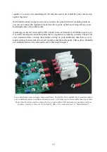
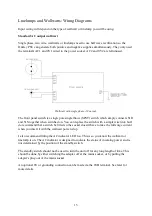
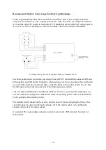
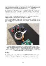
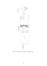
An Oakley PSU2 module connected to a single Dizzy board. Note that in this build the local 0V bond to
the panel and 4mm socket is made via the Dizzy's 'Earth' connection and not directly from the PSU2's
0VB terminal.
In an ideal world I wanted the Oakley power bus to be based on a five way 0.156” MTA or
Molex connector. This would c15V, -15V and three 0V or grounds. One ground
would be the safety ground; this would be connected to the power supply's 0V, the modules'
front panels and to the mains earth. The second would be a clean ground for all the analogue
modules to take their supply reference, the true zero volt line, ie. 0V. The third would be a
dirty ground. This would be the ground reference for things like the noisy digital circuitry and
LED switching. All three would be connected together but only at the power supply.
However, this system would be incompatible with the popular MOTM modular system which
only has a four way connector for its analogue modules. So the question now remained, how
could I make my system work with MOTM, yet still retain some of the features I needed.
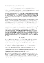
The chosen Oakley power bus comprises of +15V and -15V lines with two separate 0V
connections. These 0V are not connected together in each module as they are in MOTM
modules. They are joined only at the power supply in a wholly Oakley Modular.
In an Oakley modular one of the grounds, pin 2, is solely used for the electronics in the
module. I call this module ground or module 0V, it's the reference point for all the circuitry
used in a module. Unfortunately, it is also the dumping point for some hefty current but I try
to reduce this to a minimum by certain design choices in the modules.
25

