


Universal Serial Bus Interface
MCF5253 Reference Manual, Rev. 1
24-20
Freescale Semiconductor
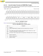
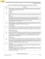
24.6.3.3
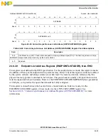
USB Interrupt Enable Register (USBINTR)
The interrupts to the software are enabled with this register. An interrupt is generated when a bit is set and
the corresponding interrupt is active. The USB Status register (USBSTS) still shows interrupt sources even
if they are disabled by the USBINTR register, allowing polling of interrupt events by the software.
1
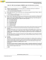
UEI
(USBERRINT)
USB Error Interrupt (USBERRINT). When completion of a USB transaction results in an error condition, this bit
is set by the controller. This bit is set along with the USBINT bit, if the TD on which the error interrupt occurred
also had its interrupt on complete (IOC) bit set. See Section 4.15.1 in EHCI for a complete list of host error
interrupt conditions. Also see
in this chapter for more information on device error matrix. For the
controller in device mode, only resume signaling is detected, all others are ignored.
1 Error detected.
0 No error.
0
UI
(USBINT)
USB Interrupt (USBINT). This bit is set by the controller when the cause of an interrupt is a completion of a USB
transaction where the Transfer Descriptor (TD) has an interrupt on complete (IOC) bit set. This bit is also set by
the controller when a short packet is detected. A short packet is when the actual number of bytes received was
less than the expected number of bytes.
Address MBAR2 0x748
Access: User read/write
31
30
29
28
27
26
25
24
23
22
21
20
19
18
17
16
R
W
Reset
0
0
0
0
0
0
0
0
0
0
0
0
0
0
0
0
15
14
13
12
11
10
9
8
7
6
5
4
3
2
1
0
R
SLE
SRE
URE
AAE
SEE
FRE
PCE
UEE
UE
W
Reset
0
0
0
0
0
0
0
0
0
0
0
0
0
0
0
0
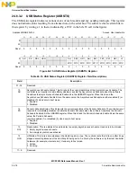
Figure 24-16. USB Interrupt Enable (USBINTR) Register
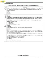
Table 24-17. USB Interrupt Enable (USBINTR) Register Field Descriptions
Field
Description
31–9
Reserved.
8
SLE
Sleep Enable. This is a non-EHCI bit. When this bit is a one, and the DCSuspend bit in the USBSTS register transitions,
the controller will issue an interrupt. The interrupt is acknowledged by the software writing a one to the DCSuspend bit.
Used only in device mode.
1 Enable.
0 Disable.
Table 24-16. USB Status Register (USBSTS) Register Field Descriptions (continued)
Field
Description
Summary of Contents for MCF5253
Page 1: ...Document Number MCF5253RM Rev 1 08 2008 MCF5253 Reference Manual...
Page 26: ...MCF5253 Reference Manual Rev 1 xxvi Freescale Semiconductor...
Page 32: ...MCF5253 Reference Manual Rev 1 xxxii Freescale Semiconductor...
Page 46: ...MCF5253 Introduction MCF5253 Reference Manual Rev 1 1 14 Freescale Semiconductor...
Page 62: ...Signal Description MCF5253 Reference Manual Rev 1 2 16 Freescale Semiconductor...
Page 98: ...Instruction Cache MCF5253 Reference Manual Rev 1 5 10 Freescale Semiconductor...
Page 104: ...Static RAM SRAM MCF5253 Reference Manual Rev 1 6 6 Freescale Semiconductor...
Page 128: ...Synchronous DRAM Controller Module MCF5253 Reference Manual Rev 1 7 24 Freescale Semiconductor...
Page 144: ...Bus Operation MCF5253 Reference Manual Rev 1 8 16 Freescale Semiconductor...
Page 176: ...System Integration Module SIM MCF5253 Reference Manual Rev 1 9 32 Freescale Semiconductor...
Page 198: ...Analog to Digital Converter ADC MCF5253 Reference Manual Rev 1 12 6 Freescale Semiconductor...
Page 246: ...DMA Controller MCF5253 Reference Manual Rev 1 14 18 Freescale Semiconductor...
Page 282: ...UART Modules MCF5253 Reference Manual Rev 1 15 36 Freescale Semiconductor...
Page 344: ...Audio Interface Module AIM MCF5253 Reference Manual Rev 1 17 46 Freescale Semiconductor...
Page 362: ...I2 C Modules MCF5253 Reference Manual Rev 1 18 18 Freescale Semiconductor...
Page 370: ...Boot ROM MCF5253 Reference Manual Rev 1 19 8 Freescale Semiconductor...