


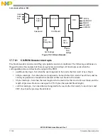


Audio Interface Module (AIM)
MCF5253 Reference Manual, Rev. 1
Freescale Semiconductor
17-35
When the Full condition is set for processor data input registers, the processor should read data from the
FIFO, before overrun occurs (this is within a 1/2 sample period). Reading of data should be done using
32-bit operands (ex. MOVE.L instruction). When the Full condition is set, and the FIFO contains, for
example six samples, it is acceptable for the software to read the first six samples from the LEFT address,
followed by six samples from the RIGHT address, or six samples from the RIGHT address, followed by
six samples from the LEFT address, or one sample LEFT, followed by one sample RIGHT repeated six
times. The order of reading does not need to be carried out in any specific order.
The implementation for PDIR1 is a double FIFO, one for left and one for right. The Full condition is set
when both FIFOs are full. The Underrun/Overrun condition is set when one of the FIFO’s actually
underrun’s or overrun’s. The resync interrupt is set when the hardware took special action to resynchronize
either the left or the right FIFO.
17.7.7.3
PDOR1, PDOR2, and PDOR3 Interrupts
Three interrupts are associated with FIFOs that can be written from PDOR1, PDOR2, PDOR3:
1. Empty
2. Under/over
3. Resync
When the Empty condition is set for processor data output registers, the processor should write data to the
FIFO, before underrun occurs. Writing of data should be done using MOVE LONG or MOVEM
instructions (with long-word oriented instructions). When Empty is set, and, for example, six samples need
to be written, it is acceptable for the software to write first six samples from the LEFT address, followed
by six samples from the RIGHT address, or one sample LEFT, followed by one sample RIGHT repeated
six times.
NOTE
In any chosen writing scheme the left should be written before the right.
The implementation of all data output FIFO’s is a double FIFO, one for left and one for right. The Empty
Interrupt is set when both FIFO’s are empty. The Underrun/Overrun interrupt is set when one of the FIFO’s
either underrun’s or overrun’s. Resync is set when the hardware resynchronizes the left and right FIFOs.
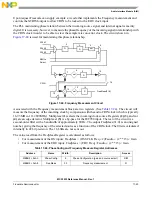
On receiving an Underrun/Overrun interrupt, synchronization between Left and Right words in the FIFOs
may be lost. Synchronization will not be lost when the underrun or overrun comes from the audio side of
the FIFO. If the processor reads or writes more data from, for example, the left than from the right,
synchronization will be lost. If automatic resynchronization is enabled, and if the software obeys the rules
to let this work, resynchronization will be automatic.
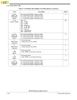
Table 17-20. Interrupt Register Field Description (0x94, 0x98)
Bit
Interrupt Name
Description
How to Clear
31
IIS1TxUnOv
IIS1 transmit
FIFO
under/overrun
reg. IntClear
30
IIS1TxResyn
IIS1 transmit
FIFO
resync
reg. IntClear
29
IIS2TxUnOv
IIS2 transmit
FIFO
under/overrun
reg. IntClear
Summary of Contents for MCF5253
Page 1: ...Document Number MCF5253RM Rev 1 08 2008 MCF5253 Reference Manual...
Page 26: ...MCF5253 Reference Manual Rev 1 xxvi Freescale Semiconductor...
Page 32: ...MCF5253 Reference Manual Rev 1 xxxii Freescale Semiconductor...
Page 46: ...MCF5253 Introduction MCF5253 Reference Manual Rev 1 1 14 Freescale Semiconductor...
Page 62: ...Signal Description MCF5253 Reference Manual Rev 1 2 16 Freescale Semiconductor...
Page 98: ...Instruction Cache MCF5253 Reference Manual Rev 1 5 10 Freescale Semiconductor...
Page 104: ...Static RAM SRAM MCF5253 Reference Manual Rev 1 6 6 Freescale Semiconductor...
Page 128: ...Synchronous DRAM Controller Module MCF5253 Reference Manual Rev 1 7 24 Freescale Semiconductor...
Page 144: ...Bus Operation MCF5253 Reference Manual Rev 1 8 16 Freescale Semiconductor...
Page 176: ...System Integration Module SIM MCF5253 Reference Manual Rev 1 9 32 Freescale Semiconductor...
Page 198: ...Analog to Digital Converter ADC MCF5253 Reference Manual Rev 1 12 6 Freescale Semiconductor...
Page 246: ...DMA Controller MCF5253 Reference Manual Rev 1 14 18 Freescale Semiconductor...
Page 282: ...UART Modules MCF5253 Reference Manual Rev 1 15 36 Freescale Semiconductor...
Page 344: ...Audio Interface Module AIM MCF5253 Reference Manual Rev 1 17 46 Freescale Semiconductor...
Page 362: ...I2 C Modules MCF5253 Reference Manual Rev 1 18 18 Freescale Semiconductor...
Page 370: ...Boot ROM MCF5253 Reference Manual Rev 1 19 8 Freescale Semiconductor...