


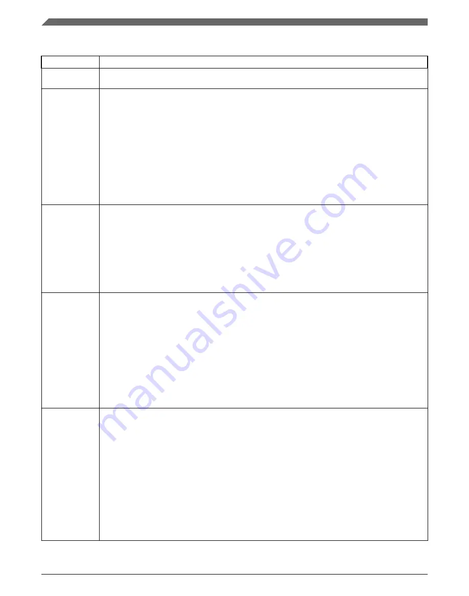
LPUARTx_STAT field descriptions (continued)
Field
Description
0
LPUART receiver idle waiting for a start bit.
1
LPUART receiver active (LPUART_RX input not idle).
23
TDRE
Transmit Data Register Empty Flag
When the transmit FIFO is enabled, TDRE will set when the number of datawords in the transmit FIFO
(LPUART_DATA) is equal to or less than the number indicated by LPUART_WATER[TXWATER]). To
clear TDRE, write to the LPUART data register (LPUART_DATA) until the number of words in the transmit
FIFO is greater than the number indicated by LPUART_WATER[TXWATER]. When the transmit FIFO is
disabled,TDRE will set when the transmit data register (LPUART_DATA) is empty. To clear TDRE, write to
the LPUART data register (LPUART_DATA).
TDRE is not affected by a character that is in the process of being transmitted, it is updated at the start of
each transmitted character.
0
Transmit data buffer full.
1
Transmit data buffer empty.
22
TC
Transmission Complete Flag
TC is cleared when there is a transmission in progress or when a preamble or break character is loaded.
TC is set when the transmit buffer is empty and no data, preamble, or break character is being
transmitted. When TC is set, the transmit data output signal becomes idle (logic 1). TC is cleared by
writing to LPUART_DATA to transmit new data, queuing a preamble by clearing and then setting
LPUART_CTRL[TE], queuing a break character by writing 1 to LPUART_CTRL[SBK].
0
Transmitter active (sending data, a preamble, or a break).
1
Transmitter idle (transmission activity complete).
21
RDRF
Receive Data Register Full Flag
When the receive FIFO is enabled, RDRF is set when the number of datawords in the receive buffer is
greater than the number indicated by LPUART_WATER[RXWATER]. To clear RDRF, read
LPUART_DATA until the number of datawords in the receive data buffer is equal to or less than the
number indicated by LPUART_WATER[RXWATER]. When the receive FIFO is disabled, RDRF is set
when the receive buffer (LPUART_DATA) is full. To clear RDRF, read the LPUART_DATA register.
A character that is in the process of being received does not cause a change in RDRF until the entire
character is received. Even if RDRF is set, the character will continue to be received until an overrun
condition occurs once the entire character is received.
0
Receive data buffer empty.
1
Receive data buffer full.
20
IDLE
Idle Line Flag
IDLE is set when the LPUART receive line becomes idle for a full character time after a period of activity.
When ILT is cleared, the receiver starts counting idle bit times after the start bit. If the receive character is
all 1s, these bit times and the stop bits time count toward the full character time of logic high, 10 to 13 bit
times, needed for the receiver to detect an idle line. When ILT is set, the receiver doesn't start counting
idle bit times until after the stop bits. The stop bits and any logic high bit times at the end of the previous
character do not count toward the full character time of logic high needed for the receiver to detect an idle
line.
To clear IDLE, write logic 1 to the IDLE flag. After IDLE has been cleared, it cannot become set again until
after a new character has been stored in the receive buffer or a LIN break character has set the LBKDIF
flag . IDLE is set only once even if the receive line remains idle for an extended period.
0
No idle line detected.
1
Idle line was detected.
Table continues on the next page...
Register definition
K32 L2A Reference Manual, Rev. 2, 01/2020
820
NXP Semiconductors
Summary of Contents for K32 L2A Series
Page 2: ...K32 L2A Reference Manual Rev 2 01 2020 2 NXP Semiconductors...
Page 42: ...K32 L2A Reference Manual Rev 2 01 2020 42 NXP Semiconductors...
Page 122: ...Flash Memory Clock K32 L2A Reference Manual Rev 2 01 2020 122 NXP Semiconductors...
Page 158: ...Debug and security K32 L2A Reference Manual Rev 2 01 2020 158 NXP Semiconductors...
Page 174: ...Module Signal Description Tables K32 L2A Reference Manual Rev 2 01 2020 174 NXP Semiconductors...
Page 246: ...Application information K32 L2A Reference Manual Rev 2 01 2020 246 NXP Semiconductors...
Page 374: ...CMP Trigger Mode K32 L2A Reference Manual Rev 2 01 2020 374 NXP Semiconductors...
Page 384: ...Functional description K32 L2A Reference Manual Rev 2 01 2020 384 NXP Semiconductors...
Page 592: ...Application Information K32 L2A Reference Manual Rev 2 01 2020 592 NXP Semiconductors...
Page 656: ...Functional Description K32 L2A Reference Manual Rev 2 01 2020 656 NXP Semiconductors...
Page 664: ...Functional Description K32 L2A Reference Manual Rev 2 01 2020 664 NXP Semiconductors...
Page 744: ...Functional description K32 L2A Reference Manual Rev 2 01 2020 744 NXP Semiconductors...
Page 762: ...Functional description K32 L2A Reference Manual Rev 2 01 2020 762 NXP Semiconductors...
Page 806: ...Functional description K32 L2A Reference Manual Rev 2 01 2020 806 NXP Semiconductors...
Page 868: ...Integer square root K32 L2A Reference Manual Rev 2 01 2020 868 NXP Semiconductors...
Page 976: ...Functional description K32 L2A Reference Manual Rev 2 01 2020 976 NXP Semiconductors...
Page 1012: ...Functional description K32 L2A Reference Manual Rev 2 01 2020 1012 NXP Semiconductors...
Page 1094: ...Functional description K32 L2A Reference Manual Rev 2 01 2020 1094 NXP Semiconductors...
Page 1132: ...Functional description K32 L2A Reference Manual Rev 2 01 2020 1132 NXP Semiconductors...
Page 1182: ...Functional description K32 L2A Reference Manual Rev 2 01 2020 1182 NXP Semiconductors...
Page 1290: ...Functional description K32 L2A Reference Manual Rev 2 01 2020 1290 NXP Semiconductors...