ISD94100 Series Technical Reference Manual
Sep 9, 2019
Page
763
of 928
Rev1.09
IS
D
9
410
0
S
ER
IE
S
T
E
C
HN
ICA
L
RE
F
E
RE
NCE
M
AN
U
AL
2. Set software trigger SWTRG2 (EADC_SWTRG[2]) to 1 to start a sample module 2 ADC
conversion, after the conversion completes, it generates an EOC2 pulse signal and ADINT0
interrupt pulse at end of sample module 2 ADC conversion, ADINT0 interrupt pulse will trigger
the sample module 0, 1, 2 to start the ADC conversions.
3. ADINT0 interrupt pulse repeats to trigger sample module 0, 1, 2 ADC conversions
automatically.
4. Clear TRGSEL (EADC_SCTL2[20:16]) to 0 to disable sample module 2 ADINT0 interrupt pulse
hardware trigger, if needs to stop the continuous scan.
Note:
Because the system costs 3 ADC_CLK to trigger next module by interrupt pulse, the average
conversion cycles of continuous scan triggered by interrupt is 17 ADC_CLK.
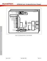
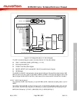
ADINT0
.
ADINT3
Sample module 0 EOC
ADC Interrupt
control Logic
ADCIEN0
(EADC_CTL[2])
ADINT0
ADIF0
(EADC_STATUS[0])
SPLIE0
(EADC_INTSRC0[0])
Sample module 12 EOC
SPLIE12
(EADC_INTSRC0[12])
...
..
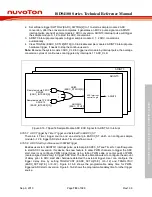
Figure 6.16-7 Specific Sample Module ADC EOC Signal for ADINT0~3 Interrupt
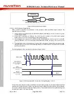
6.16.5.7 ADC Trigger by Timer Trigger and External Pin EADC0_ST
There are 4 Timer trigger source and an external pin EADC0_ST which can configure sample
module 0~12 to trigger ADC start when Timer overflow occurs.
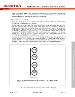
6.16.5.8 ADC Start Synchronous with PWM Trigger
Besides user start, ADINT0/1 interrupt pulse, external pin EADC0_ST and Timer0~3 overflow pulse
to start ADC conversion, this device has new feature to allow PWM channels to trigger the ADC
start. User may configure PWM trigger types: rising, falling PWM edge or center point of PWM
(center-aligned mode only) to trigger ADC start. The device also allow user to configure the amount
of delay prior to ADC start after hardware detected the external trigger. User can configure the
trigger delay time by setting TRGDLYCNT (EADC_SCTLn[15:8], n=0~12) and TRGDLYDIV
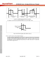
(EADC_SCTLn[7:6], n=0~12). Figure 6.16-8 shows the programmable delay time for PWM-
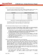
triggered ADC start conversion. Figure 6.16-9 shows the programmable delay time for other trigger
source.

