ISD91200 Series Technical Reference Manual
Release Date: Sep 16, 2019
- 455 -
Revision 2.4
SWTRG
sample
chsel[3:0]
0000b 0010b 0011b 0111b 0000b 0010b 0011b 0111b 0000b
ADDR0
ADDR2
ADDR3
ADDR7
Software clear
SWTRG
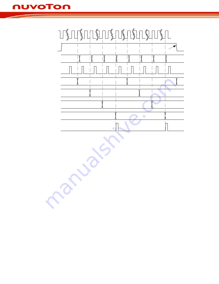
Continuous scan on channel 0, 2, 3 and 7 (SARADC_CHEN[15:0] =
0010001101b)
ADEF
27
ADC_CLK
28 55 56
1
84
112 1 28
56
84
112
Figure 7-24 Continuous Scan on Enabled Channels Timing Diagram
7.8.3.5
External trigger Input Sampling and A/D Conversion Time
In Single-cycle scan mode, A/D conversion can be triggered by external pin request. When the CTL.HWTRGEN is set
to high to enable SARADC external trigger function. setting the HWTRGSEL[1] bits to 0b is to select external trigger
input from the STADC pin. Software can set HWTRGCOND[1:0] to select trigger condition is falling/rising edge or
low/high level. If level trigger condition is selected, the STADC pin must be kept at defined state at least 8 PCLKs.
The ADST bit will be set to 1 at the 9th PCLK and start to conversion. Conversion is continuous if external trigger
input is kept at active state in level trigger mode. It is stopped only when external condition trigger condition
disappears. If edge trigger condition is selected, the high and low state must be kept at least 4 PLCKs. Pulse that is
shorter than this specification will be ignored.
7.8.3.6
Conversion Result Monitor by Compare Function
SARADC controller provide two sets of compare register SARADC_CMP0 and SARADC_CMP1, to monitor
maximum two specified channels conversion result from A/D conversion controller, refer Figure… Software can
select which channel to be monitored by set CMPCH(SARADC_CMPx[5:0]) and CMPCOND bit is used to check
conversion result is less than specify value or greater than (equal to) value specified in CMPDAT[11:0]. When
the conversion of the channel specified by CMPCH is completed, the comparing action will be triggered one time
automatically. When the compare result meets the setting, compare match counter will increase 1, otherwise, the
compare match counter will be cleared to 0. When counter value reach the setting of (1) then
ADCMPF bit will be set to 1, if ADCMPIE bit is set then an ADC_INT interrupt request is generated. Software can
use it to monitor the external analog input pin voltage transition in scan mode without imposing a load on
software. Detailed logics diagram is shown below:


