


DSP LASER AP with MCS
10.4.2.5. Automatic tool clamping
Tool Clamping
To activate the control function of the upper and lower tool holders, assign the value “ON” to
the programming parameter B7.
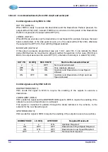
If the function is active, when the control signals connected to ING1 and ING6 switch from
state OFF (0V = clamps closed) to state ON (+24V = grippers open) and, as consequence,
the control signals of the relevant pressure switches connected to INS23 and INS24 switch
from state ON (+24V = clamps closed) to state OFF (0V = clamps open), MCS enters in
state STOP (only the upstroke movement is allowed).
When the control signals connected to ING1 and ING6 return to state OFF (0V) and, as
consequence, the control signals of the relevant pressure switches connected to INS23 and
INS24 return to state ON (+24V), MCS can restore the normal operation.
Warning
:
The installer is responsible to verify that the crossbeam upstroke
command does not create dangers even with the clamps open.
Otherwise this function cannot be enabled.
Caution:
If the parameter B7 is set to value “ON CNC”, the control signals must not
be connected to the inputs ING1 and ING6, because they are transmitted
by CNC via RS232 interface.
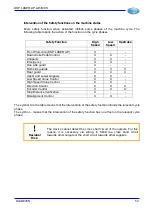
Led Upper and Lower Tool holder
Fixed ON: Corresponding Tool Holder open.
OFF: Corresponding Tool Holder closed.
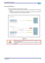
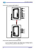
Figure 37
48
DLAM01EN
Summary of Contents for DSP LASER AP
Page 2: ......
Page 4: ......
Page 50: ...DSP LASER AP with MCS Figure 34 44 DLAM01EN...


