


Power
Status
Low Energy Positive Input Ventilation Unit
DRIMASTER 365
Installation and Maintenance Details
1
Leaflet Number 671347 October 2007
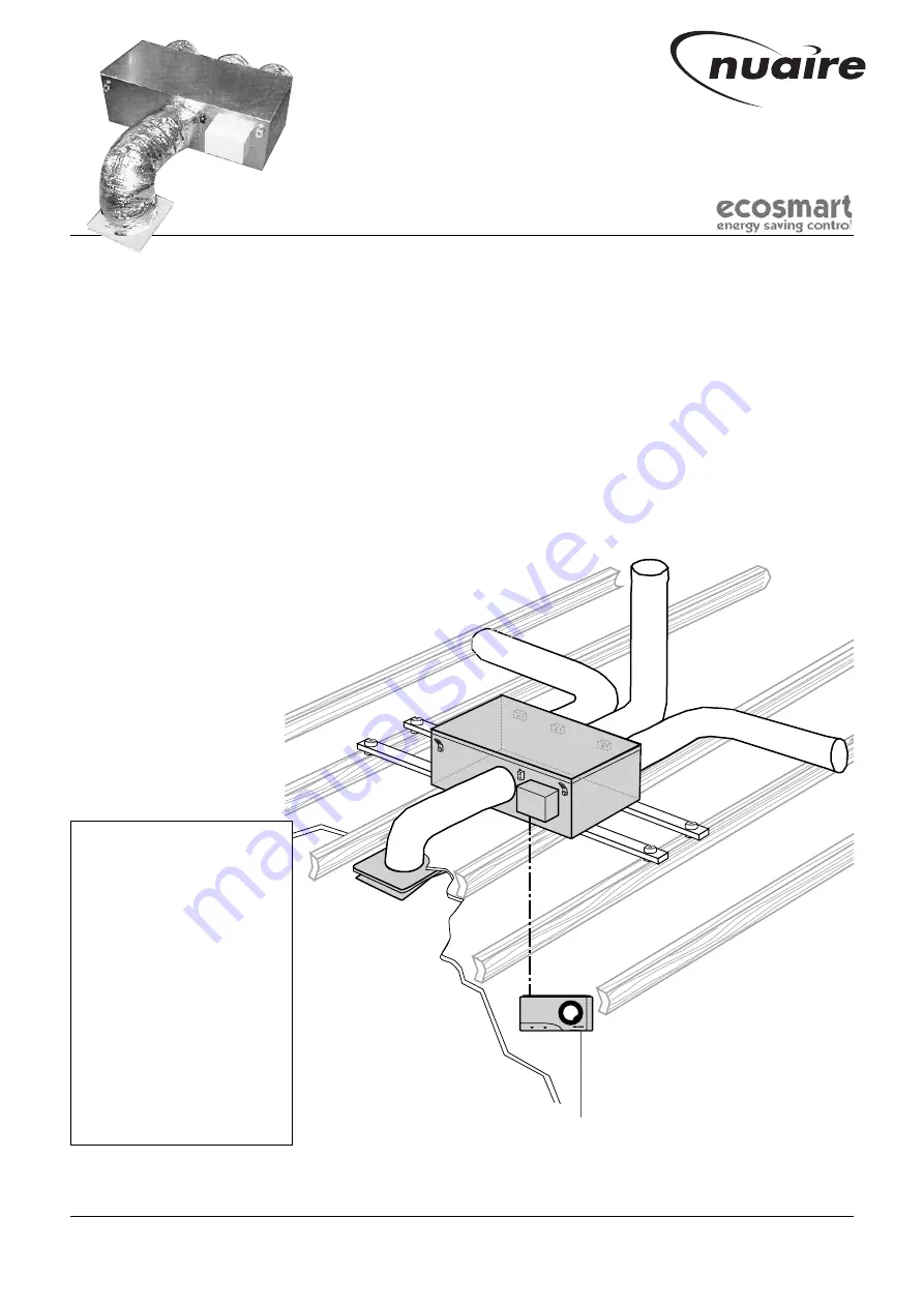
Figure 1. General view of unit in a loft.
(Shown located on AV mounts).
User control panel, located in the home.
Please note:
1. Only the items shown shaded
are supplied as standard with
the unit.
All other installation materials
(see table on page 3) must be
purchased separately by the
installer.
2. The 4 temperature sensors
(one for each of the air inlet
locations and one for the
home itself) and associated
sensor cables (15m long) are
also supplied with the unit.
3. The cable (10m long)
connecting the unit to the user
control is also supplied.
1.0 Important notes to installers
The successful operation of this unit depends entirely upon
installation and ongoing maintenance being carried out strictly
in accordance with these instructions.
Please read this guide in its entirety before installation and then
repeat the exercise step by set to ensure satisfactory completion.
Suitably qualified persons may achieve installation of the unit,
however the provision of the electrical supply and the connection of
the unit to the mains supply should only be carried out by a qualified
electrician.
The unit can be installed in a home with a “cold roof” or “warm
roof”. These instructions are limited to installation in a home
with a “cold roof”. “Warm roofs” vary considerably and advice
should be sought from Nuaire on an individual basis.
2.0 General description
The unit is a unique Low Energy Positive Input Ventilation (LEPIV)
unit. Unlike conventional LEPIV units which only draw in external
air via the loft in a “cold roof’, the unit is capable of drawing in
external air from different roof locations via three air inlet spigots
each fitted with their own low energy open/close damper. (See fig. 1).
The units airflow and the opening/closing of each air inlet damper
is controlled via an integral intelligent control system that measures,
and appropriately responds to, temperatures at the various air inlet
locations, the home itself, the “target temperature” selected by the
occupants on the user control panel provided and the delivered air
temperature into the home.
Nuaire Limited
Western Industrial Estate Caerphilly United Kingdom CF83 1NA
T: 029 2088 5911 F: 029 2088 7033 E: [email protected] W: www.nuaire.co.uk