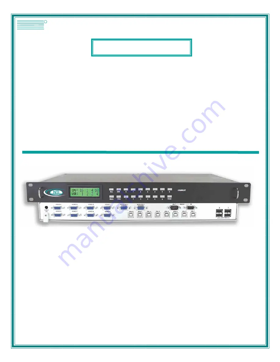
NTI UNIMUX-2X16-U Installation And Operation Manual Download Page 1


MAN028 Rev 3/26/07 


UNIMUX-nXm-U  

Multi-user USB KVM Switch 

Installation and Operation Manual 

Software Version 1.34


UNIMUX

TM

Series


NETWORK
TECHNOLOGIES
INCORPORATED

Tel:330-562-7070
Fax:330-562-1999

1275 Danner Dr
Aurora, OH 44202

  www.networktechinc.com

NTI

R

Summary of Contents for UNIMUX-2X16-U

Page 1: ...U Multi user USB KVM Switch Installation and Operation Manual Software Version 1 34 UNIMUXTM Series NETWORK TECHNOLOGIES INCORPORATED Tel 330 562 7070 Fax 330 562 1999 1275 Danner Dr Aurora OH 44202...

Page 2: ...tem or transmitted in any form or by any means electronic mechanical photocopying recording or otherwise without the prior written consent of Network Technologies Inc 1275 Danner Drive Aurora Ohio 442...

Page 3: ...1 Password and User Name 11 User Login Mode 12 Additional OSD Modes Available With Security Enabled 12 Administration Mode 12 Administrator Password 13 User Name List 14 Edit User 14 Alternate Command...

Page 4: ...IGURES Figure 1 Mount Switch to a Rack 5 Figure 2 Install user monitor s 6 Figure 3 Install user devices mouse and keyboard 7 Figure 4 Use USB A A 5M to extend a device or a computer 7 Figure 5 Group...

Page 5: ...2 RS232 connection with Matrix Y 1 cable 26 Figure 23 Pinout of Matrix Y 1 cable 27 Figure 24 Cascading with only multi user units 31 Figure 25 Cascaded configuration with single user masters 32 Figur...

Page 6: ...en used with NTI DVIF 15HDM adapter Most USB mice and keyboards Polyvision Whiteboard with USB support ORDERING INFORMATION The UNIMUX USB KVM switch is built to a specific size ranging from 2 to 8 us...

Page 7: ...file of this manual Materials Not Supplied but REQUIRED USBVEXT xx MM cable for each CPU being connected to the switch Where xx is the length of the cable in feet 3 6 10 or 15 feet available MM indic...

Page 8: ...user monitors 10 VIDEO x 15HD female connectors for attachment of video cables from CPUs F r o n t V i e w o f U N I M U X 1 2 N T I R N e t w o r k T e c h n o l o g i e s I n c U N I M U X T M 1 2 3...

Page 9: ...each CPU preventing connected CPUs from locking up Any user device cable can be hot plugged Typically the LCD display indicates the CPU to which each user is connected 10 configurations can be saved...

Page 10: ...10 32 x3 4 screws supplied Each screw should be of sufficient length to go completely through the NTI mounting flange rack frame and fully engage all threads in the captive nut Be sure to tighten all...

Page 11: ...r monitor s R e a r V i e w o f U N I M U X M O N I T O R 1 M O N I T O R 2 M O N I T O R 3 M O N I T O R 4 V I D E O 1 V I D E O 2 V I D E O 3 V I D E O 4 V I D E O 5 V I D E O 6 V I D E O 7 V I D E...

Page 12: ...NCORPORATED Tel 330 562 7070 www nti1 com 1275 Danner Drive Fax 330 562 1999 R Aurora Ohio 44202 USB A A 5M USB DEVICE CPU USB KEYBOARD USB TYPE A MALE CONNECTOR USB TYPE A FEMALE CONNECTOR TO UNIMUX...

Page 13: ...s f o r C P U 2 C o n n e c t i o n s C P U 1 C P U 2 C P U 3 V I D E O 1 V I D E O 2 V I D E O 3 V I D E O 4 R e a r V i e w o f U N I M U X M O N I T O R 1 M O N I T O R 2 M O N I T O R 3 M O N I T...

Page 14: ...o an AC power outlet Turn ON power to the UNIMUX switch the LCD should illuminate Turn ON power to any or all CPUs connected to the UNIMUX switch if they aren t ON already Note The order in which the...

Page 15: ...following single digit user entries ENTER Used following single digit entries Display next 4 users and the CPUs they are connected to See note below Display previous 4 users and the CPUs they are conn...

Page 16: ...accent key The OSD menu will automatically appear on the monitor This provides a visual way to control the UNIMUX USB KVM switch using the keyboard and mouse The administrator will activate security...

Page 17: ...d the administrator is logged in Users other than the administrator are not allowed to enter the Administration Mode If a different user is logged in log out by pressing Q from the Maintenance Mode me...

Page 18: ...ters in length Note The default password for the administrator is ADMINISTRATOR Function Keystroke Switch between Password and Verify Password fields Figure 11 Administrator password menu Add characte...

Page 19: ...r mode press E from the User Name List after selecting a user or an empty record The Edit User mode see Figure 13 enables the administrator to add a new user remove an existing user edit the settings...

Page 20: ...in the User Access List Save the edited configuration Administrator will be prompted for a Yes or No confirmation Go back to User Name List menu Note To delete a user from the User Name List use eithe...

Page 21: ...he mouse to click on the arrows on the scroll bar in the OSD menu When the Command Mode main menu is displayed the first displayed port in the list will be the port the current user is connected to fo...

Page 22: ...administrator is logged in Enter Change Settings Menu Figure 15 Command Mode additional options Enter Maintenance Mode Display Help Menu Select a specific port Select the first port on the switch Sele...

Page 23: ...y is pressed or the mouse is moved whichever comes first The scan dwell time is programmable from 2 to 255 seconds default time out period is 5 seconds When the user uses the mouse or keyboard the sca...

Page 24: ...in length Characters typed can be upper or lower case After changes have been made the administrator will be prompted by the menu to save the changes Answer Y to save changes and answer N to continue...

Page 25: ...r to select specific ports to be active in Scan Mode Only the selected ports will be scanned in Scan Mode A check list with all the port numbers preceded by a check box will be displayed in the window...

Page 26: ...ress C to uncheck all the ports When Esc is pressed the display will return to the Change Settings menu The list is automatically saved The settings apply to all users of the switch Maintenance Mode T...

Page 27: ...rough a list of CPU names The CPU name best matching the characters typed is selected The list of CPUs may also be searched for a specific or similar name The following commands are valid when the sea...

Page 28: ...code to be used Typically only SUN CPUs require a specific country code to be registered at boot up For other types of CPUs this feature may have no effect A list of available languages is displayed a...

Page 29: ...R Alt R Alt R Option Alt Graph SB Alt Windows Logo Command Meta SB R Arrow SB R Arrow Power Suspend SB Space Bar L and R Left and Right keys when two keys are marked the same on a keyboard Mouse Click...

Page 30: ...L o c k T a b E s c C t r l A l t B a c k s p a c e N u m L o c k A l t F 1 F 2 F 3 F 4 F 5 F 6 F 7 F 8 F 9 F 1 0 F 1 1 F 1 2 S c r o l l L o c k P a u s e B r e a k P r i n t S c r e e n S y s R q A...

Page 31: ...connector pins 1 DCD 4 DTR and 6 DSR are shorted and pins 7 RTS and 8 CTS are shorted Therefore CPU handshaking is bypassed and TXD and RXD are the only active signals A straight through DB 9 cable n...

Page 32: ...trix Y 1 cable U n i t 1 S o u r c e 2 3 3 3 5 5 5 2 2 7 8 1 4 6 J u m p e r J u m p e r s N o t c o n n e c t e d t o s o u r c e c o n n e c t o r U n i t 2 9 D F e m a l e 9 D M a l e 9 D M a l e W...

Page 33: ...the User port that is connected to the CPU port GM SW 00 CR go SW OP IP CR all connections List all switch User port connections all User ports to all CPU ports If the first field is not a known comm...

Page 34: ...t COM port baud rate and unit address About SerTest display the program version Matrix Operations Key Selection Description 1 Connect Output User to an Input CPU connect an output to an input 2 Connec...

Page 35: ...set COM port baud rate and unit address 3 Quit quit the program If Matrix Options is selected the following menu which has 7 options is displayed MATRIX OPTIONS 1 Reset single unit reset single matri...

Page 36: ...ndalone switches Users connected to accessible ports on downstream slaves i e ports not connected to the master will not be able to control switches or CPUs connected upstream Only control over CPUs a...

Page 37: ...only control CPUs 25 40 U S E R 1 U S E R 2 U S E R 3 U S E R 4 U S E R 5 U S E R 6 U N I M U X 8 X 1 6 U N I M U X 4 X 8 S L A V E S L A V E C P U P O R T S C P U P O R T S U S E R P O R T S U S E R...

Page 38: ...K T E C H N O L O G I E S I N C O R P O R A T E D T e l 3 3 0 5 6 2 7 0 7 0 F a x 3 3 0 5 6 2 1 9 9 9 1 2 7 5 D a n n e r D r A u r o r a O H 4 4 2 0 2 w w w n t i 1 c o m R R E A R V I E W O F M A S...

Page 39: ...is ready to operate If security mode is activated the login window will be displayed on the screen The update configuration function can be recalled at any time by entering into Command Mode and press...

Page 40: ...be performed by factory trained and authorized service personnel Only those items specifically identified in this manual if any may be adjusted by the user of this product and adjusted only as instru...

Page 41: ...into live outlet and powered ON Mouse only moves up and down on computer s connected to the switch through a ST C5USBV Extender Driver communication not correct between mouse and CPU Port set for non...

Page 42: ...assword and User Name 11 RMTEST 30 RS232 Command Protocol 28 RS232 Interface 26 Search Mode 22 Security features 11 Select Language 23 SerTest 29 Sharing Mode 19 size range 1 Sun s extra keys 24 Troub...

Reviews: