MAN124 Rev Date 3/4/2011
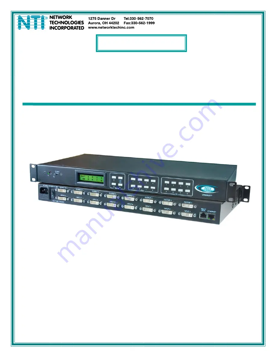
SM-nXm-DVI-LCD
DVI Video Matrix Switch
Installation and Operation Manual
VEEMUX
®
Series
Page 1: ...MAN124 Rev Date 3 4 2011 SM nXm DVI LCD DVI Video Matrix Switch Installation and Operation Manual VEEMUX Series...
Page 2: ...al system or transmitted in any form or by any means electronic mechanical photocopying recording or otherwise without the prior written consent of Network Technologies Inc 1275 Danner Drive Aurora Oh...
Page 3: ...trol 16 Telnet Interface Port 2000 16 Telnet Interface Port 2005 17 Command Summary 17 Command Detail 18 RU Read Unit Size 18 RO Read Connection for Output Port 18 CS Connect Output Port to Input Port...
Page 4: ...al to VEEMUX 6 Figure 6 Connect VEEMUX to local area network 6 Figure 7 Attach AC power cord to VEEMUX 7 Figure 8 RS232 connection with Matrix Y 1 cable 12 Figure 9 Pinout of Matrix Y 1 cable 12 Figur...
Page 5: ...quality on flat panel displays Supports DVI operation at the maximum TMDS rate of 1 65 Gb second Silent fanless operation Provides high digital resolution up to 1920x1200 for monitors and 1080p for H...
Page 6: ...is manual and control software 20pcs zip ties Materials Not supplied but REQUIRED DVI IS xx MM cable for each monitor and CPU being connected to the switch available in 3 6 10 and 15 foot lengths DVI...
Page 7: ...s video sources to connect to which outputs display devices when pressed 9 IEC Connector for connection of AC power cord 10 Power Switch for turning the VEEMUX ON or OFF 11 Input DVI I Female connecto...
Page 8: ...ld line up with pre threaded holes in the sides of the NTI switch Tighten the screws securely Figure 1 Secure rack mount ears to switch 2 Install 4 cage nuts supplied to the rack in locations that lin...
Page 9: ...INPUT 3 INPUT 4 RS232 ETHERNET DCE OUTPUT 1 OUTPUT 2 OUTPUT 3 OUTPUT 4 OUTPUT 5 OUTPUT 6 OUTPUT 7 OUTPUT 8 REAR VIEW OF SM 8X8 DVI LCD Mating Face of DVI I Single Link Male DVD Player DVI IS xx MM DVI...
Page 10: ...traight through pin 1 to pin 1 pin 2 to pin 2 etc Figure 6 Connect VEEMUX to local area network RJ45 USB RJ45 US B FUSE T2A 250V AC INPUT 100 240VAC 30W INPUT 1 INPUT 6 INPUT 7 INPUT 8 INPUT 5 INPUT 2...
Page 11: ...Power ON the VEEMUX video sources and display devices RJ45 US B R J 4 5 U S B FUSE T2A 250V AC INPUT 100 240VAC 30W INPUT 1 INPUT 6 INPUT 7 INPUT 8 INPUT 5 INPUT 2 INPUT 3 INPUT 4 RS232 ETHERNET DCE O...
Page 12: ...ons have been saved page 23 upon power up the VEEMUX will load the configuration saved into memory location 0 Along with the routing of the inputs video sources to the outputs monitors the keypad and...
Page 13: ...to exit this screen Selections 3 4 are necessary to apply valid values for your Subnet Mask and Gateway Navigate these settings as described for setting the IP address Selections 5 and 6 are not used...
Page 14: ...t option is not applicable The main menu has two additional options 5 Save Config and 6 Load Config described below The list of current connections shown on the LCD screen can be scrolled using the Up...
Page 15: ...o most CPUs see page 6 To daisy chain multiple units connect a Matrix Y 1 cable sold separately between the CPU and the first switch and between each switch as shown in Figure 8 Baud Rate The baud rat...
Page 16: ...9D Female 9D Male 9D Male Wiring Schematic of Matrix Y 1 cable NTI SWITCH CPU RS232 First Unit NTI SWITCH RS232 NTI SWITCH RS232 Second Unit Last Unit RS232 Serial Port Matrix Y 1 Matrix Y 1 Matrix Y...
Page 17: ...ding zeroes are accepted EM SW ip CR Set the Subnet mask ip is in xxx xxx xxx xxx format number of digits is minimum 1 and maximum 3 for each field Leading zeroes are accepted EG SW ip CR Set the defa...
Page 18: ...rogram after downloading 1 Locate the Setup exe in the directory the program was downloaded to and double click on it 2 Follow the instructions on the screen The Matrix Switcher s Control Program perf...
Page 19: ...oduct Ethernet Operations Key Selection Description 1 Set Unit IP Address enter the desired IP address in xxx xxx xxx xxx format number of digits is minimum 1 and maximum 3 for each field Leading zero...
Page 20: ...ect One Input nn To Output mm CA nn CR Connect All Outputs To Input nn RO nn CR mm CR Read Connection For Output Returns the number of the input mm connected to output nn CC nn CR nn CR Save Matrix Co...
Page 21: ...MAXOUTPUTS IP Input Port 01 MAXINPUTS CR Carriage Return Hex 0xD Command Summary Command String Good Response Description RU CR ru OP IP CR Read unit size RO OP CR pc OP IP CR Read connection for OP...
Page 22: ...5 Byte 6 Byte 7 Byte 8 Byte 9 p 0x70 c 0x63 Space 0x20 Output 1st digit 0x30 0x32 Output 2nd digit 0x30 0x39 0x2C Input 1st digit 0x30 0x32 Input 2nd digit 0x30 0x39 CR 0x0D This command will read the...
Page 23: ...0x63 Space 0x20 Output 1st digit 0x30 0x32 Output 2nd digit 0x30 0x39 0x3A Input 1st digit 0x30 0x32 Input 2nd digit 0x30 0x39 CR 0x0D SS_00 Disable Auto Status Mode Command Byte 1 Byte 2 Byte 3 Byte...
Page 24: ...nate telnet session Command Byte 1 Byte 2 Byte 3 X 0x58 X 0x58 CR 0x0D Response Byte 1 Byte 2 0x2A CR 0x0D The unit will respond with CR and close the connection terminating the telnet session The uni...
Page 25: ...address into the address bar of the web browser Address To open a SSL encrypted connection type Address You will be prompted to accept a certificate Accept the NTI certificate A Login Page will appear...
Page 26: ...ection configurations can be saved and later recalled by any connection method Scanning Sequences page 28 for each output can also be enabled Note Changes made using the keypad page 8 or by another us...
Page 27: ...currently active configuration on the VEEMUX If changes have been made in the web interface without first pressing the Submit button those changes will not yet be part of the active configuration Not...
Page 28: ...ch cable connection from display devices for easy reference Scanning Sequence Assign dwell times for each input as it is assigned to each output s scanning sequence DDC Options Configure how each inpu...
Page 29: ...ration page Mode Choose between Static IP assignment and DHCP IP Address If using Static IP assignment enter a valid IP address to use Subnet Mask Enter a valid subnet mask value Default Gateway Enter...
Page 30: ...ction will stay logged in The range is 0 999 minutes 0 disables it Any change to the Website Timeout configuration takes effect immediately Press the Save button to save any changes made Video Input N...
Page 31: ...ut ports displayed on the Switch page Figure 15 Video Output Names page To change an Output Name enter the name of the port for the desired output port number and press Save If you make changes and ch...
Page 32: ...ount of time that each will be viewed 0 32000 seconds can be set to cycle sequentially for each connected output If an input is set to 0 seconds that input will not be viewed and will be skipped from...
Page 33: ...ons and establish a connection and starting point for the scanning sequence Blocks shown in yellow in the third image indicate connections made 3 Click on the Sequence Enable box for each output from...
Page 34: ...e The video source on input 1 is connected to output 8 then 4 then 2 and then 5 for a total of 4 display connections If output 8 is switched to another video source the video source on input 1 will th...
Page 35: ...r to change the password used to access the VEEMUX This password is also used for the telnet interface Be sure to make note of the new password exactly as it is case sensitive The password must be bet...
Page 36: ...r 2 On the Update Firmware page in the Update File block browse to the firmware file 3 Press Upgrade Note If an update is attempted using the wrong firmware for the section an error message will be re...
Page 37: ...the VEEMUX is placed in Standby Mode When in Standby Mode the VEEMUX is still operating as configured but cannot be manipulated further until standby is disabled Standby Mode can be disabled either by...
Page 38: ...Matrix Switch at NTI From there you can see what versions of firmware are available and determine if the version in your VEEMUX is current or in need of an upgrade page 32 Figure 22 Support Tab Reboo...
Page 39: ...page Note The Discovery Tool requires the Java Runtime Environment to operate A copy of Java and a link to the web page from which it can be downloaded and installed is provided on the CD Note The co...
Page 40: ...Standby Features Routing of video signals together or individually Ability to switch one input to all outputs Scroll through inputs for a single output by using the Input keys similar to changing chan...
Page 41: ...can be recalled 0 9 SYS Pressed to select the desired NTI system to be controlled Only used when controlling multiple systems Must be followed by a system number 1 15 ENTER Pressed to immediately acce...
Page 42: ...utton before selecting the output port number by pressing the OUT button after selecting the output port number In both cases the user must enter the output port number using the Numeric Keys 0 9 Howe...
Page 43: ...input port number Example Quick method to change Input 1 from Output x any to Output 8 1 IN 8 OUT must enter the OUT command within 5 seconds of pressing IN Connect Input to Multiple Outputs Several d...
Page 44: ...imeout and the number entered will be recalled to the current configuration Multiple Switch Control All compatible NTI matrix switches will work with the same IRT UNV IR Remote control As a result a u...
Page 45: ...l above GENERAL TECHNICAL SPECIFICATIONS Video Video Amplifier Bandwidth 165MHz Input Video Signal 1 2 volts p p Input DDC Signal 5 volts p p TTL Single Link Range 1080p 1920 x 1200 DVI Connector DVI...
Page 46: ...Scanning Sequences 29 SerTest 15 standby mode 34 Telnet Interface 17 Telnet Port 2005 18 username and password 22 Video Switch 23 web browsers 1 WARRANTY INFORMATION The warranty period on this produ...