MAN064 Rev Date11/10/2005
ST-
x
U
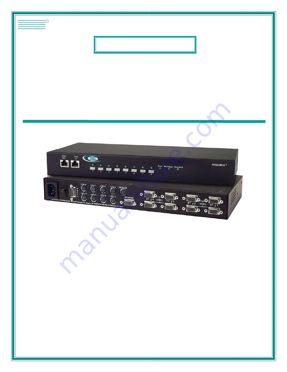
Universal KVM Switch
Installation and Operation Manual
NODEMUX
®
Series
NETWORKTECHNOLOGIESINCORPORATED
Tel:330-562-7070Fax:330-562-1999
1275 Danner DrAurora, OH 44202
www.nti1.com
NTI
R
Page 1: ...Date11 10 2005 ST xU Universal KVM Switch Installation and Operation Manual NODEMUX Series NETWORK TECHNOLOGIES INCORPORATED Tel 330 562 7070 Fax 330 562 1999 1275 Danner Dr Aurora OH 44202 www nti1...
Page 2: ...n a retrieval system or transmitted in any form or by any means electronic mechanical photocopying recording or otherwise without the prior written consent of Network Technologies Inc 1275 Danner Driv...
Page 3: ...de 18 Administrator Password 18 User Name List 19 System Access List 19 User Access Functions 19 OSD Command Mode 19 Scan Mode 22 Broadcast Mode 22 Normal Mode 22 Edit Mode 22 Search Mode 23 Maintenan...
Page 4: ...reen 17 Figure 20 Switch configured as a master with one slave attached 17 Figure 21 Administrator password change 18 Figure 22 Command Mode menus 20 Figure 23 Video and Device connections identified...
Page 5: ...h Screen support Built in serial port for use with 3M MicroTouch touch screen monitor with EX II 8000SR Controller Add TSO to the part number i e ST xU TSO Note OSD Touch Screen support option is only...
Page 6: ...mouse interface One of the following cables must be used to connect the input devices keyboard and mouse PS 2 keyboard mouse VKTINT 1 OR SUN keyboard mouse None needed SUN keyboard plugs directly in O...
Page 7: ...n only 1 2 3 4 5 6 7 8 S c a n C o m m a n d B r o a d c a s t 1 8 O N 2 3 4 5 F r o n t V i e w o f l e g a c y N O D E M U X 1 N T I R N e t w o r k T e c h n o l o g i e s I n c 6 C P U 1 C P U 2 C...
Page 8: ...he screws securely Figure 1 Secure rackmount ears to switch 2 Install 4 captive nuts not provided to the rack in locations that line up with the holes in the mounting ear on the NTI switch 3 Secure th...
Page 9: ...h Configuration to configure the switch for cascading 4 Connect the monitor to the port labeled MONITOR on the rear of the NODEMUX See Fig 4 Figure 4 Connect the monitor V G A M u l t i S c a n M o n...
Page 10: ...0 5 6 2 7 0 7 0 w w w n t i 1 c o m S T 8 U R E A R V I E W D E V I C E S 8 P i n m i n i D I N F e m a l e C o n n e c t o r P S 2 K e y b o a r d V K T I N T 1 P S 2 M o u s e 6 P i n m i n i D I N...
Page 11: ...U 1 C P U 2 C P U 3 C P U 4 C P U 5 C P U 6 C P U 7 C P U 8 N T I 5 V D C 2 A D E V I C E S R 7 V I D E O 8 V I D E O 7 V I D E O 6 V I D E O 5 V I D E O 4 V I D E O 3 V I D E O 2 V I D E O 1 M O N I...
Page 12: ...not use with NTI products Generic 9D to 6mD adapter 9D Male 6 Pin miniDIN Male C P U 1 C P U 2 C P U 3 C P U 4 C P U 5 C P U 6 C P U 7 C P U 8 N T I 5 V D C 2 A D E V I C E S R 7 V I D E O 8 V I D E...
Page 13: ...all CPUs connected to the NODEMUX FYI If upon startup the monitor immediately displays a USER LOGIN menu requiring a USER NAME and PASSWORD then the administrator has already setup the system and enab...
Page 14: ...E SUN CPU SUCEXT xx NOT USED SUKINT xx MM SE 4M15D 8 A SLAVE MAC CPU MEXT xx MM NOT USED MKINT xx MM ST xU SLAVE PS 2 CPU VEXT xx MM NOT USED VKTINT xx MM Limitations a Master units can be any size si...
Page 15: ...1 default settings Switch 1 5 6 STAND ALONE SWITCH OFF OFF OFF SLAVE ON OFF OFF MASTER W 4 PORT SLAVES OFF OFF ON MASTER W 8 PORT SLAVES OFF ON OFF MASTER W 16 PORT SLAVES OFF ON ON Table 2 default s...
Page 16: ...E O 6 V I D E O 5 V I D E O 4 V I D E O 3 V I D E O 2 V I D E O 1 M O N I T O R DAISY DAISY OUT IN NETWORKTECHNOLOGIES INCORPORATED 1275 Danner Drive Aurora Ohio 44202 330 562 7070 www nti1 com TO SL...
Page 17: ...mode LEDs are illuminated the user is in Normal Mode controlling directly the CPU to which the user is connected through the NODEMUX Keyboard Control Keyboard control of the NODEMUX can be achieved th...
Page 18: ...ping the appropriate port number See Fig 17 above No programming of the Universal KVM switch is necessary to achieve this control When cascading if not all of the ports are used on each slave attached...
Page 19: ...of the CPU s name and the OSD will locate it Help screens assist with all OSD functions Security Option The security option of the OSD Control enables an administrator to control access to the CPU por...
Page 20: ...e password Submit user name password Exit User Login Mode and return to previous mode This function is only available if security is not currently active Additional Modes Available With Security NOTE...
Page 21: ...a master with one slave attached A unit configured as a MASTER W 4 PORT SLAVES can have up to 8 slaves attached each with up to 4 ports for CPUs A MASTER W 8 PORT SLAVES can also have up to 8 slaves...
Page 22: ...hanges made Changes made will take effect the next time the NODEMUX is power cycled To continue setting up a cascaded system of switches see Cascaded Installation on page 10 Administrator Password To...
Page 23: ...ge access rights by clicking on a given number to toggle a port s status A user that has access to a port can connect to that port and control the CPU connected to that port when in Normal Mode Functi...
Page 24: ...ribes the Command functions available from the keyboard within the OSD menu after entering into Command Mode and while the COMMAND LED is illuminated Function Keystroke Select the previous port Select...
Page 25: ...mand Mode To change the displayed ports on the screen simply click on the up and down arrows located to the right of the port names displayed NOTE The port mentioned in the Command Functions above ref...
Page 26: ...uring the scan time out period NOTE The keyboard and mouse must remain idle for the full scan time out period before the switch will connect to the next active port Broadcast Mode use with extreme cau...
Page 27: ...best matching CPU name is selected The list of CPUs may also be searched for a specific or similar name The following commands are valid when the search option has been invoked from Command Mode Func...
Page 28: ...ke OSD window shorter Change user password Present only when a standard user is logged in Log current user out and return to User Login Mode Activate security features Present only when security is av...
Page 29: ...creen support option has been built into the NODEMUX Touch Maintenance Mode is used to communicate the operating values of the connected touch screen monitor to the NODEMUX and to synchronize the curs...
Page 30: ...eeds to be done once for the monitor connected If the monitor is changed it must be repeated for the new monitor Steps 3 and 4 establish the location of the OSD menu when the CPU connected to the sele...
Page 31: ...ork for most CPUs To daisy chain multiple units a Matrix Y 1 cable is used see page 29 for each NODEMUX in the chain The last unit will have no connection on its output port and should have DIP switch...
Page 32: ...NODEMUX the terminal and NODEMUX must each be configured for the same baud rate Press W from the Administration Mode menu page 15 to enter Switch Configuration mode Fig 31 Press Tab once to move the...
Page 33: ...as needed for the application Figure 32 Daisy chain configuration with Matrix Y 1 cable Unit Address In order for a terminal to communicate with one or more NODEMUX switches each switch must have a u...
Page 34: ...ns FORMAT RS AA CR RS reset unit command followed by at least one space AA unit address if 00 all units on the bus will be reset and no response will be returned RESPONSE CR if command received and ex...
Page 35: ...RU read unit size command followed by at least one space AA unit address RESPONSE CR command received and executed OK XX YY CR XX of CPU s YY of USERS OR CR syntax or transmission error occurred RV r...
Page 36: ...a keyboard Mouse Click Equivalents To emulate right button click using an Apple 1 button mouse hold down the CMND key while pressing the mouse button SB Space Bar Figure 35 Keyboard key layouts MAC o...
Page 37: ...roadcast Modes or the Scan and or Broadcast Modes can be individually disabled leaving the other features in Command Mode enabled To disable these operating modes the user must get access to the jumpe...
Page 38: ...panel with 15HD connectors on it Disconnect the flat ribbon cables from the video board to each header on the rear panel Take note as to where they go for re assembly later Do not disconnect them from...
Page 39: ...ps head screws from the underside of the ST xU O that hold the plastic case together Remove the 4 torx head screws from the underside as well These hold the lower circuit board to the plastic case Tur...
Page 40: ...the jumper block Now follow the instructions on page 36 under CONFIGURING THE JUMPER BLOCK Figure 42 Clear access to jumper block N u t s 4 s e c u r e t h e c i r c u i t b o a r d t o t h e s t a n...
Page 41: ...e monitor has touch screen features The Keyboard mouse ports may alternatively be used for the data communications DATA I O if a keyboard and mouse are present At least one set of DATA I O ports must...
Page 42: ...re unsure how to do this contact your system administrator PROBLEM Monitor shuts down while working with OSD menu Disengage or increase time setting of CPU monitor s sleep mode from the BIOS and or co...