background image

MAIN MENU 

33


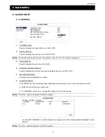
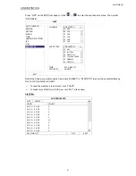
FTP 

When this function is enabled and an event occurs, a html file including a link will be sent to the specified FTP site. 
Click the link to access to this DVR and check the event recording. 

ADVANCED CONFIG 


CAMERA  

WAN 

FTP 

E-MAIL 

DDNS   

DETECTION  

FTP 

ALERT 

ON 

ALERT  

USER 

NAME 

MANAGER 

NETWORK 

 PASSWORD 

●●●●●●


DISPLAY  

SERVER 

192.168.2.32 

RECORD  

PORT 

0021 

DEVICES  

DIRECTORY 

UPLOAD 

DCCS  


IVS  


NOTIFY  


EXIT  


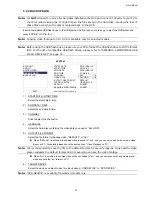
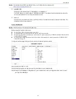
E-MAIL 

When this function is enabled and an event occurs, a html file including a link will be sent to the specified E-mail 
address. Click the link to access to this DVR and check the event recording. 

ADVANCED CONFIG 


CAMERA  

WAN 

FTP 

E-MAIL 

DDNS   

DETECTION  

E-MAIL 

ALERT 

ON 

ALERT  

SMTP 

SERVER 

SMTP.GMAIL.COM 

NETWORK 

 PORT 

465 

DISPLAY  

MAIL 

FROM 

MANAGER 

RECORD  

SSL 

ENCRYPTION 

ON 

DEVICES  

VERIFY 

PASSWORD  ON 

DCCS  

USER 

NAME 

MANAGER 

IVS  

PASSWORD 

●●●●●●


NOTIFY  

RECEIVER 

SETUP 


EXIT  


1) E-MAIL 

ALERT 

Select “ON” to enable this function, or “OFF” to disable this function. 

2) SMTP 

SERVER 

Enter the SMTP server address provided from your e-mail system supplier. 

3) PORT 

Enter the port number provided from your e-mail system supplier. If this column is left blank, the e-mail 
server will use port 25 to send e-mails. 

4) MAIL 

FROM 

Enter the sender’s name. 

5) SSL 

ENCRYPTION 

Select “ON” if your e-mail server is using SSL encryption to protect your e-mail content from unauthorized 
access. 

6) VERIFY 

PASSWORD 

Some mail servers are required to verify the password. Please enter the “user name” and “password”. 

7)  USER NAME / PASSWORD 

Enter the “user name” and “password” when “VERIFY PASSWORD” is set to “ON”. 

8) RECEIVER 

Select “SETUP” to add up to 15 e-mail addresses of the assigned recipients. 

Summary of Contents for FULL D1 DVR

Page 1: ...LL D1 DVR User Manual Intelligent Video Surveillance GUI Display with USB Mouse Control Please read instructions thoroughly before operation and retain it for future reference For the actual display operation please refer to your DVR in hand ...

Page 2: ... when the equipment is operated in a commercial environment This equipment generates uses and can radiate radio frequency energy and if not installed and used in accordance with the instruction manual may cause harmful interference to radio communications Operation of this equipment in a residential area is likely to cause harmful interference in which case the user will be required to correct the...

Page 3: ...CENSING MAY BE OBTAINED FROM MPEG LA LLC SEE HTTP WWW MPEGLA COM GPL Licensing This product contains codes which are developed by Third Party Companies and which are subject to the GNU General Public License GPL or the GNU Lesser Public License LGPL The GPL Code used in this product is released without warranty and is subject to the copyright of the corresponding author Further source codes which ...

Page 4: ...age 10 3 1 1 DVR Status 10 3 1 2 Channel Status 11 3 1 3 Record related Icons 11 3 3 Quick Menu Bar 11 3 4 Main Menu 12 4 FREQUENTLY USED FUNCTIONS 13 4 1 Key Lock Unlock 13 4 2 User Level Creation 13 4 3 PTZ Control 14 4 4 Playback 15 4 4 1 Playback Control 15 4 4 2 Event Search 16 4 4 3 Audio Playback 16 4 5 Video Backup 16 4 6 Video Playback on PC dv5 17 4 6 1 Convert the file format to AVI 17 ...

Page 5: ...l Operation 50 6 1 4 E Map 52 6 2 Web Browser 58 6 2 1 Event Playback Download 60 6 2 2 IVS Statistics 61 APPENDIX 1 SPECIFICATIONS 62 APPENDIX 2 PIN CONFIGURATION 64 APPENDIX 3 PUSH VIDEO CONFIGURATION 65 A3 1 PIN Connection 65 A3 2 Configuration 67 APPENDIX 4 MOBILE SURVEILLANCE VIA EAGLEEYES 68 A4 1 Prerequisites 68 A4 2 Where to download 68 APPENDIX 5 SET PUSH VIDEO 70 A5 1 Prerequisite 70 A5 ...

Page 6: ...ay 3 Press to show the 4 channel display mode 4 SEQ Press to display each channel in full screen one by one starting from CH1 When the last channel is displayed it will repeat from CH1 again To exit this mode press SEQ again 5 SLOW In the playback mode press to show slow playback 6 ZOOM Press to enlarge the picture of selected channel in the FRAME or FIELD recording mode 7 PLAY Press to playback t...

Page 7: ...3 Rear Panel 1 75Ω HI IMPEDANCE For selected models only When using VIDEO LOOP switch to HI IMPEDANCE If not switch to 75Ω 2 VIDEO IN Connect to the video connector of a camera VIDEO LOOP For selected models only Video output connector Note The DVR will automatically detect the video system of the camera please make sure that the cameras are properly connected to the DVR and power supplied before ...

Page 8: ... an external hard disk or a disk array Note Please purchase a disk array supporting Linux system to ensure your DVR to work properly 10 Push Video Alarm In For selected models only Connect up to four external alarm devices for active event notifications to your smart phone Push Video The four alarm inputs 1 4 are corresponding to the four video inputs CH1 4 11 EXTERNAL I O This port is used to con...

Page 9: ...th other data previously saved in the same hard disk For details please refer to 2 6 Clear Hard Disk at page 8 Step1 Loose the screws on the upper cover and open the upper cover of the DVR Note The DVR cover is made of metal Please be careful with its edge when you remove the cover Step2 There are two hard disk brackets for this DVR as indicated in the right picture 2 1 To install on the first bra...

Page 10: ...g our brand s PTZ camera as an example Note The RS485 wiring is not needed when your DVR and PTZ camera both support DCCS and the video channel your PTZ camera connects is CH1 If yes please go to STEP 5 directly for PTZ camera setting For detailed PIN port connection please refer to APPENDIX 2 PIN CONFIGURATION at page 64 For detailed PTZ camera control and operation please refer to its own user m...

Page 11: ...et the baud rate to the value the same as the one set in the camera The default baud rate of the camera is 2400 ADVANCED CONFIG CAMERA CH1 CH2 CH3 CH4 CH5 CH6 CH7 CH8 CH9 CH10 CH11 DETECTION DEVICE PTZ ALERT ID 000 NETWORK PROTOCOL NORMAL DISPLAY RATE 2400 RECORD DEVICES DCCS IVS NOTIFY EXIT 2 3 External Device Connection This device supports external device connection with RS485 and alarm I O por...

Page 12: ...recording function is activated Otherwise the recorded data will be disordered and you will not be able to find the recorded file to backup by time search If users change the date or time accidentally when the recording function is activated it s recommended to clear all HDD data and start recording again Note For the first time to use the DVR please power it on for at least 48 hours continuously ...

Page 13: ... R 5 BACKUP DATA AUTO KEY LOCK S NEVER BACKUP LOG CLEAR HDD HDD 0 RESET DEFAULT SUBMIT REMOTE CONTROL ID 000 SERIAL TYPE RS485 VIDEO FORMAT NTSC VERSION 1019 1008 1010 1010 EXIT 2 7 Password Setting Right click to show the main menu and select SYSTEM ACCOUNT to change the default password of SUPERVISOR There are four user levels for different access privileges SUPERVISOR POWER USER NORMAL GUEST Fo...

Page 14: ...ection is ok If you see make sure The distance between this DVR and the DCCS camera should not exceed 200 meters with a 3C2V coaxial cable 112 braids Note However different materials used in 3C2V coaxial cables with different connection distance may cause some effects for the availability and fluency of signal transmission It s not allowed to use a signal booster or modem to amplify signals and ex...

Page 15: ...m key lock to unlock Note You may configure four different user levels to have different access privileges in SYSTEM ACCOUNT For details please refer to 4 2 User Level Creation at page 13 Password Input 3 2 Live Page 3 1 1 DVR Status Note Certain icons are for selected models only Key lock Key unlock Overwrite on Overwrite off Internet disconnected Internet connected Local connection USB mouse con...

Page 16: ...will see on the screen 4 HDD Overwritten Be defaults the HDD overwritten function is set to ON and will be shown on the screen Note To disable this function right click to display the main menu in the live view and go to ADVANCED CONFIG RECORD OVERWRITE 3 3 Quick Menu Bar Move to the arrow mark to extend the quick menu bar and show the five functions as follows Quick Menu Open Click to show the ch...

Page 17: ...lick to set the status display image settings and date time SYSTEM Click to set the system configurations EVENT INFORMATION Click to enter the event search menu ADVANCED CONFIG Click to set CAMERA DETECTION ALERT NETWORK DISPLAY RECORD DEVICES DCCS IVS NOTIFY SCHEDULE SETTING Click to set record timer detection timer alarm timer For selected models only ...

Page 18: ...reation at page 13 4 2 User Level Creation Note This function is available only for SUPERVISOR To create different user account for different access privilege click SYSTEM and select ACCOUNT to enter USER LIST SYSTEM ACCOUNT USER LIST TOOLS USER NAME LEVEL SYSTEM INFO admin SUPERVISOR BACKUP DATA power POWER USER BACKUP LOG normal NORMAL guest GUEST EXIT ADD EDIT DEL Different user level has diffe...

Page 19: ...ur selection up down left right or change settings Digital zoom in out Click to zoom in out the camera image digitally Focus near far Click to adjust the focus of the image Preset point Click to display the preset point panel for preset point viewing or setting For details please refer to the section below How to set a preset point Step1 Step2 Click or to the proper ratio you need and click to mov...

Page 20: ...l be shown on the screen 4 4 1 Playback Control Fast Forward Increase the speed for fast forward Click once to get 4X speed forward and click twice to get 8X speed etc and the maximum speed is 32X Fast Rewind Increase the speed for fast rewind Click once to get 4X speed rewind and click twice to get 8X speed etc and the maximum speed is 32X Play Pause Click to play the latest recorded video clip i...

Page 21: ...patible USB flash drives please refer to APPENDIX 6 COMPATIBLE USB FLASH DRIVE LIST at page 72 Note Video backup could be made via the built in DVD writer optional a USB flash drive or the Internet It s NOT allowed to connect the hard disk to your PC directly for it may impair the recorded data saved in the hard disk To copy recorded data for video backup click SYSTEM and select BACKUP DATA USB or...

Page 22: ...he hark disk causing the loss of those files even when the disk is replaced back to the DVR To play dv5 video on your PC Step1 Insert the USB flash drive or CD DVD with recorded data into your PC Note The supported PC operating systems are Windows 7 Vista XP Step2 Find the program PLAYER EXE in the USB flash drive and double click it to install Note PLAYER EXE can also be downloaded from www surve...

Page 23: ...FREQUENTLY USED FUNCTIONS 18 To exit this mode right click anywhere on the screen Note You need to exit the zoom mode first to use other DVR functions ...

Page 24: ...OFF 4 BUTTON CONTROL DISPLAY Select to display the control icons on each single channel or not ON OFF 5 MOUSE SENSITIVITY Select the mouse sensitivity by 9 levels 6 RECORD CONFIG Click SETUP to enter the setting page individually for manual record event record and timer record a Select the record type you want to set b In CHANNEL select ALL to apply the changes here to all channels Note The I P S ...

Page 25: ...T GENERAL DATE 2009 NOV 17 TIME SETUP TIME 15 35 53 DAYLIGHT NTP SERVER tock stdtime gov tw FORMAT Y M D SYNC PERIOD DAILY GMT GMT 08 00 TAIPEI EXIT 7 DATE Set the current date The default display format is YEAR MONTH DATE Y M D 8 TIME Set the current time in HOUR MIN SEC 9 NTP SERVER Click to change the default NTP server to another server they re familiar with or keep the default NTP server 10 F...

Page 26: ...art time and end time 3 ADJUST Set the time in HOUR MIN 5 2 SYSTEM 5 2 1 ACCOUNT This function is used to create a new user account or modify or delete an existing account for different access privilege Note For details about available local operations of each user level please refer to 4 2 User Level Creation at page 13 ADVANCED CONFIG ACCOUNT USER LIST TOOLS USER NAME LEVEL SYSTEM INFO admin SUP...

Page 27: ...COMPATIBLE USB FLASH DRIVE LIST at page 72 Note After upgrading firmware it s recommended to clear all HDD data for the system to work more stably Before clearing all HDD data please remember to make video backup 3 NETWORK UPGRADE Click SUBMIT for perform system upgrade via Internet Note This function requires Internet access Please make sure your DVR is connected to Internet before using this fun...

Page 28: ... are not mixed with other data previously saved in the same hard disk The DVR firmware is upgraded for the system to work more stably Before clearing all HDD data please remember to make video backup DVR date and time are changed accidentally when the recording function is activated Otherwise the recorded data will be disordered and you will not be able to find the recorded file to backup by time ...

Page 29: ...LL HARD DISK ALL HDD OUTPUT FILE FORMAT DEFAULT TARGET DEVICE USB DEVICE BACKUP SUBMIT REQUIRE SIZE 554MB SUBMIT EXIT AVAILABLE SIZE 3788 0MB 1 START DATE START TIME Select the start date time 2 END DATE TIME Select the end date time 3 CHANNEL Click to select the channel s 4 HARD DISK Select the hard disk containing the video data you need or ALL HDD 5 OUTPUT FILE FORMAT Select the file format for...

Page 30: ...B flash drive or CD DVD with recorded data into your PC Note The supported PC operating systems are Windows 7 Vista XP Step2 Find the program PLAYER EXE in the USB flash drive and double click it to install Note PLAYER EXE can also be downloaded from www surveillance download com user c700 swf Step3 Run the program VideoPlayer and browse to where you save the recorded data Step4 Select the file yo...

Page 31: ...OV 19 BACKUP DATA USB END TIME 17 59 29 BACKUP LOG USB CHANNEL ALL DATA TYPE 3 SELECTED ALL MANUAL MOTION ALARM SYSTEM TIMER BACKUP SUBMIT EXIT 1 START DATE START TIME Select the start date time 2 END DATE TIME Select the end date time 3 CHANNEL Click to select the channel s 4 DATA TYPE Click SETUP to select the event type you want MANUAL MOTION ALARM SYSTEM TIMER HUMAN DETECTION INFLOW OUTFLOW VI...

Page 32: ... you want from the calendar and the time with recorded data will be highlighted from the time scale bar Step4 To immediately play the video clip click SUBMIT To choose the start time for video playback move your mouse cursor to the highlighted time and click to confirm the time when the time display below is the time you want The video playback is activated right away when you confirm the time Not...

Page 33: ...NT INFORMATION QUICK SEARCH NUMBER MODEL TEMP SIZE FREE FORMAT TIME SERIAL NUMBER F W EVENT SEARCH HDD 0 ST31000526SV 46 890 562GB 864 832GB 2011 DEC 13 18 18 53 9V0DN5WS ST31000526SV HDD INFO EVENT LOG EXIT 5 3 4 EVENT LOG You can check all system events SYSTEM and backup logs BACKUP or clear all log records EVENT INFORMATION QUICK SEARCH SYSTEM BACKUP EVENT SEARCH EVENT TIME COMMENT HDD INFO KEY...

Page 34: ... details please refer to 5 4 5 DISPLAY at page 34 3 REC Select if you want to enable recording for the selected channel ON OFF Note When this function is disabled no manual event or timer recording will be activated even if any of these three record functions is set to ON 4 CHANNEL TITLE Click the channel title column to change the channel title up to 12 characters The default title is the channel...

Page 35: ...epending on your installation need The default alarm value is OFF 6 AREA Click EDIT to set the motion detection area There are 16 12 grids per camera for all channels Pink blocks represent the area that is not being detected while the transparent blocks are the area under detection 5 4 3 ALERT ADVANCED CONFIG CAMERA EXT ALERT ON DETECTION INT BUZZER OFF ALERT KEY BUZZER ON NETWORK VLOSS BUZZER ON ...

Page 36: ... C ADVANCED CONFIG CAMERA WAN FTP E MAIL DDNS DETECTION NETWORK TYPE STATIC ALERT IP 192 168 001 010 NETWORK GATEWAY 192 168 001 254 DISPLAY NETMASK 255 255 255 000 RECORD PRIMARY DNS 168 095 001 001 DEVICES SECONDARY DNS 139 175 055 244 DCCS PORT 0080 IVS APPLY NOTIFY EXIT MAC 00 0E 53 EC A7 B4 1 NETWORK TYPE Select the network type as STATIC and set all the information needed in the DVR 2 NETWOR...

Page 37: ...TTP is 80 However in some cases it is better to change this port number for added flexibility or security 4 USER NAME PASSWORD Set username and password subscribed from your ISP supplier D DH HC CP P Note When DHCP configuration is completed please move to DDNS to configure the DDNS service ADVANCED CONFIG CAMERA WAN FTP E MAIL DDNS DETECTION NETWORK TYPE DHCP ALERT IP 192 168 001 010 NETWORK GATE...

Page 38: ...T 465 DISPLAY MAIL FROM MANAGER RECORD SSL ENCRYPTION ON DEVICES VERIFY PASSWORD ON DCCS USER NAME MANAGER IVS PASSWORD NOTIFY RECEIVER SETUP EXIT 1 E MAIL ALERT Select ON to enable this function or OFF to disable this function 2 SMTP SERVER Enter the SMTP server address provided from your e mail system supplier 3 PORT Enter the port number provided from your e mail system supplier If this column ...

Page 39: ...ice instead of using ours please refer to www surveillance download com user CMS pdf and check Appendix 2 for details ADVANCED CONFIG CAMERA WAN FTP E MAIL DDNS DETECTION DDNS ON ALERT SYSTEM NAME eagleeyes NETWORK HOST NAME MAC000E53ECA7B4 DISPLAY EMAIL EMPTY RECORD DEVICES DCCS IVS NOTIFY CURRENT HOST ADDRESS EXIT MAC000E53ECA7B4 ddns eagleeyes tw 5 4 5 DISPLAY ADVANCED CONFIG CAMERA FULL SCREEN...

Page 40: ... users change the date or time accidentally when the recording function is activated it s recommended to clear all HDD data and start recording again ADVANCED CONFIG CAMERA MANUAL RECORD ON DETECTION EVENT RECORD ON ALERT TIMER RECORD ON NETWORK PRE ALARM RECORD ON DISPLAY OVERWRITE ON RECORD KEEP DATA LIMIT DAYS OFF DEVICES RECORD CONFIG SETUP DCCS IVS NOTIFY EXIT 1 MANUAL RECORD Set the manual r...

Page 41: ... 37 Different zoom lens control cameras might have different parameter settings For details please refer to their own user manuals 2 ID Click the current value to set the ID number 0 255 for the connected PTZ camera if necessary Make sure the ID setting of the camera is the same as the setting here or the DVR will not be able to control the device Note To know the default ID of the PTZ camera plea...

Page 42: ...figure the connected zoom lens control camera Different zoom lens control cameras might have different parameter settings For details please refer to their own user manuals Note While configuring the camera parameters the DVR will switch to the corresponding channel and you can simultaneously preview the effects for the settings 3 DEVICE Here shows the model number of the camera 4 CONNECTION Here ...

Page 43: ...S MODE Select one of the following three modes depending on your environment MODE DESCRIPTION FLOW COUNTING A virtual detection line is set to detect the moving direction of pedestrians for flow counting VIRTUAL FENCE A virtual detection line is set to detect intruders crossing the detection line and an alarm will be triggered ONE WAY A virtual detection line is set to detect intruders from the sp...

Page 44: ...ep1 Go to VIRTUAL FENCE AREA to draw a detection line with your mouse and decide the detection direction by selecting REVERSE Step2 Finish the IVS setting and return to the live view The IVS icon will be shown on the status bar Click it to show the flow counting panel as follows When anyone walks across the detection line the system will determine his movement is in or out and add one count to the...

Page 45: ...ing REVERSE Step2 Finish the IVS setting and return to the live view When anyone walks across the detection line the system will determine his movement is in or out and VIRTUAL FENCE An event happens for anyone walking across the detection line and will be shown on the screen ONE WAY An event happens for anyone walking from the opposite direction to the arrow mark and will be shown on the screen ...

Page 46: ...NEWAY MOTION TIME 2010 MAY 17 STATISTIC SUBMIT EXIT Set all the criteria you want to search and click SUBMIT in STATISTIC to show the event statistics by DAY in LIST default or CHART To check the statistics in the bar chart click CHART To switch to the MONTH or HOUR view click DAY at the bottom List View IVS STATISTIC LIST CHART HOUR COUNT 00 00 00 59 0 01 00 01 59 0 02 00 02 59 0 03 00 03 59 0 04...

Page 47: ... service provider The mobile app EagleEyes is installed in your mobile device For details please refer to APPENDIX 4 MOBILE SURVEILLANCE VIA EAGLEEYES at page 68 You have configured EagleEyes to access this DVR and Push Video is enabled For details please refer to APPENDIX 5 SET PUSH VIDEO at page 70 You ll get an active event notification with video telling you the occurrence of alarm event s ADV...

Page 48: ...rom your mobile service provider The mobile app EagleEyes is installed in your mobile device For details please refer to APPENDIX 4 MOBILE SURVEILLANCE VIA EAGLEEYES at page 68 You have configured EagleEyes to access this DVR and Push Video is enabled For details please refer to APPENDIX 5 SET PUSH VIDEO at page 70 You ll get a text message telling you the occurrence of selected system event s ADV...

Page 49: ... ON ALERT EVENT ALL NETWORK VIDEO LOSS DISPLAY HDD FULL RECORD POWER ON DEVICES CLEAR HDD DCCS NET LOGIN IVS KEY UNLOCK NOTIFY NETWORK UPS SYSTEM ABNORMAL RECEIVER SETUP EXIT VIDEO MAIL Note For E mail notifications make sure you have configured an E mail account in NETWORK E MAIL to send the notifications Enable this function in E MAIL ALERT and add the E mail address es to which you want to send...

Page 50: ...t the channel you want Step3 Click Open to download the motion recording to your computer and start playing 5 5 SCHEDULE SETTING 5 5 1 RECORD Select ON to enable record timer and select the day and time for this function SCHEDULE SETTING RECORD RECORD TIMER ON DETECTION 0 2 4 6 8 10 12 14 16 18 20 22 24 ALARM SUN MON TUE WED THU FRI SAT EXIT X axis 0 24 hours Each time bar is 30 minutes Y axis Mon...

Page 51: ...0 22 24 ALARM SUN MON TUE WED THU FRI SAT EXIT X axis 0 24 hours Each time bar is 30 minutes Y axis Monday Sunday 5 5 3 ALARM Select ON to enable alarm timer and select the day and time for this function SCHEDULE SETTING RECORD ALARM TIMER ON DETECTION 0 2 4 6 8 10 12 14 16 18 20 22 24 ALARM SUN MON TUE WED THU FRI SAT EXIT X axis 0 24 hours Each time bar is 30 minutes Y axis Monday Sunday ...

Page 52: ...p3 Follow the on screen instructions to finish the installation When the installation is completed a shortcut icon will be placed on your PC desktop 2 Network Connection L Lo oc ca al l C Co on nn ne ec ct ti io on n v vi ia a L LA AN N LAN is used when it s the first time to remotely access the DVR and you need to configure the network setting of your DVR based on your network type in advance a C...

Page 53: ...side of the control panel b Click to key in the IP address user name password and port number of the DVR you intend to connect OR Click to search the available IP address es of other DVR s under the same domain as your PC s IP address The found address es will be listed and can be added into the address book by clicking c Double click the IP address you just added into the address book to log in 6...

Page 54: ...etting Click to choose the language of this program The language change will take effect when this program is closed and executed again Log Click to view all event and recording logs search the desired log s by date or playback the recording of the selected log Record Record Stop Click to start stop the manual recording Snapshot Click to take a snapshot of the current view The snapshot will be sav...

Page 55: ... click or on the main control panel to start the manual recording immediately and the recordings will be saved in the specified location If Motion and or Alarm are checked the recording function will also be enabled at the remote side when any event is triggered at the DVR side and the recordings will be saved in the specified location Playback To play a recording click or and select the Record ta...

Page 56: ...ber Channel within which have the video data you need Download by Time Specify the time range within which has the video data you want in the Start Time and End Time columns Download by Event Select an event log from the event list This list shows all logs in the specified DVR from the latest to the earliest To quickly find the events you need check or uncheck the event type System Manual Alarm Mo...

Page 57: ...DVR for function scalability Note Before using this function make sure you have the correct upgrade files provided by your installer or distributor Step1 Click and select the IP address of your device in the address book Step2 Click to show the upgrade page Update Server Step3 Click Add to browse to the upgrade files Step4 Click Upgrade Firmware to start firmware upgrade Note It takes a few minute...

Page 58: ... In the simplified version click to switch the control panel to the full function version and click to enter the E Map page as follows Note To know where the buttons are please refer to Simplified Version Default at page 48 and Full Function Version at page 49 STEP2 Right click to show the shortcut menu on the top left panel and select the E Map group you want to add There are three E Map groups y...

Page 59: ...REMOTE OPERATION 54 STEP3 When the E Map group is created you will see the tree on the top left panel showing all the devices you ve added to this group ...

Page 60: ... to catch your attention To know what s happening quickly double click the device icon on the E Map to show the live view How to Edit Remove an Existing E Map Group For Google E Map Group Right click on the group name to show the shortcut menu list and select Edit E MAP or Remove E MAP as needed You can also add a single E Map group Add Single E MAP or Building E Map group Add Building E MAP into ...

Page 61: ...ht click on the group name to show the shortcut menu list and select Edit E MAP or Remove E MAP as needed For Building E Map Group Right click on the group name to show the shortcut menu list and select Edit Building E MAP or Remove E MAP as needed ...

Page 62: ...REMOTE OPERATION 57 To edit or remove a certain level of the building E Map group right click on the level name and select Edit E MAP or Remove E MAP as needed ...

Page 63: ...and password the same as the ones used at AP login and click OK You will see a similar screen as the following when the login information is correct Icon Description Click to go to the live view of the DVR Click to enter the playback panel where you can search or select the event you want to play and download to your PC simultaneously For details please refer to 6 2 1 Event Playback Download at pa...

Page 64: ...this display mode press any other channel display button Click to show 4 cut 9 cut 16 cut display Playback Control Increase the speed for fast rewind Click once to get 4X speed rewind and click twice to get 8X speed etc and the maximum speed is 32X Increase the speed for fast forward Click once to get 4X speed forward and click twice to get 8X speed etc and the maximum speed is 32X Click to play t...

Page 65: ... to get 4X speed forward and click twice to get 8X speed etc and the maximum speed is 32X Play Click to play the current video clip Pause Click to pause the video playback Stop Click to stop the video playback Step In the pause mode click to get one frame forward Audio Click to mute the playback if necessary and click again to restore Note Audio is available when your camera supports audio recordi...

Page 66: ...REMOTE OPERATION 61 6 2 2 IVS Statistics Note This function is for selected models only ...

Page 67: ...Field CIF 960H Frame Field CIF Frame Field CIF 960H Frame Field CIF Recording Mode Manual Timer Motion Alarm Remote Pre alarm Recording YES Quick Search Time Motion Alarm search mode Backup Device USB 2 0 flash drive Network DVD Writer Optional USB 2 0 flash drive Network USB 2 0 flash drive Network Audio Audio Input 4 audio inputs Audio Output 2 audio outputs Mono General Hard Disk Storage Accomm...

Page 68: ...Windows and MAC operating systems QuickTime For both Windows and MAC operating systems Max online users 10 Web Transmitting Compression Format H 264 Network Live Audio YES Remote Independent Operation YES Remote Event Download Playback YES R E T R Remote Event Trigger Recording YES Mobile Surveillance App EagleEyes Compatible Devices iPad iPhone BlackBerry Symbian Windows Mobile Android mobile dev...

Page 69: ... CH5 PIN 5 7 CH7 PIN 6 9 CH9 PIN 7 11 CH11 PIN 8 13 CH13 PIN 9 15 CH15 10 11 PIN OFF NA 12 RS485 A 13 EXTERNAL ALARM NO Under the normal operation COM disconnects with NO But when any alarm is triggered COM connects with NO Attention The voltage restriction is under DC24V 1A 14 PIN OFF NA 15 22 ALARM INPUT Connect ALARM INPUT PIN 15 22 and GND PIN 1 connector with wires Once an alarm is triggered ...

Page 70: ...xternal I O port PUSH VIDEO alarm in terminal A PUSH VIDEO alarm in terminal is provided on the DVR rear panel as shown in the right picture to help you quickly find and connect to the pins which support Push Video Alarm Corresponding video channel Alarm 1 CH1 Alarm 2 CH2 Alarm 3 CH3 Alarm 4 CH4 GND Alarm 1 4 External I O port Check the table below to know which pin for alarm devices supports Push...

Page 71: ...APPENDIX 3 PUSH VIDEO CONFIGURATION 66 ...

Page 72: ... Go to ADVANCED CONFIG NOTIFY to enable GUARD to ON and configure your alarm sensor type N C or N O ADVANCED CONFIG CANERA PUSH VIDEO PUSH MESSAGE MESSAGE MAIL VIDEO MAIL DETECTION GUARD ON ALERT CH01 ALARM OFF INTERNAL ALARM CH1 NETWORK CH02 ALARM OFF CH2 DISPLAY CH03 ALARM N O office RECORD CH04 ALARM OFF CH4 DEVICES DCCS IVS NOTIFY EXIT Step2 Open EagleEyes and add this DVR to the EagleEyes add...

Page 73: ...ce make sure you have checked the following Your mobile platform is iPhone iPad BlackBerry and Android Mobile Internet services are subscribed and available to use for your mobile phone Note You might be charged for Internet access via wireless or 3G networks For the Internet access rate details please check with your local network operator or service provider You have noted down the IP address po...

Page 74: ... downloading When the download is completed EagleEyes will be installed automatically to the location where all applications are saved in your phone by default or where you specify Note For more details about configuring this program scroll down the download page to see related instructions ...

Page 75: ... CH1 for models which support DCCS or an external alarm device is connected to PUSH VIDEO Alarm In on the rear panel Make sure a camera is also connected to record for alarm occurrences To know which video channel corresponds to which alarm pin please refer to APPENDIX 3 PUSH VIDEO CONFIGURATION at page 65 The event record function of your DVR is not disabled The motion detection function of your ...

Page 76: ...APPENDIX 5 SET PUSH VIDEO 71 A5 2 2 From Android Mobile Device In the address book switch Guard from OFF to ON ...

Page 77: ...at the USB flash drive as FAT32 Note You can backup up to 2GB video data for one time USB backup To backup more data please set the time channel s you want and start USB backup again MANUFACTURER MODEL CAPACITY Transcend JFV35 4GB JFV30 8GB Kingston DataTraveler 1GB PQI U172P 4GB Apacer AH320 2GB AH320A 8GB AH220 1GB AH320 4GB A data RB 18 1GB Sandisk Cruzer Micro 2GB Cruzer Micro 4GB Cruzer4 pk 2...

Page 78: ...ACITY Seagate ST250DN000 250GB ST3320613AS 320GB ST33500320AS 500GB ST3500410SV 500GB ST3750330AS 750GB ST31000525SV 1TB ST31000340AS 1TB ST2000VX000 2TB ST2000DM001 2TB WD WD2500AAKX 250GB WD3200AAKS 320GB WD5000AZRX 500GB WD5000AACS 500GB WD6400AAKS 640GB WD7500AAKS 750GB WD10EADS 1TB WD10EALX 1TB WD15EADS 1 5TB WD20EADS 2TB WD20EURS 2TB WD2002FAEX 2TB WD20EARS 2TB Maxtor STM3500320AS 500GB STM3...

Page 79: ...ORE CONFIG SYSTEM INFO BAUD RATE HOST ID R E T R AUTO KEY LOCK S CLEAR HDD RESET DEFAULT REMOTE CONTROL ID SERIAL TYPE VIDEO FORMAT VERSION BACKUP DATA BACKUP LOG EVENT INFORMATION QUICK SEARCH EVENT SEARCH HDD INFO EVENT LOG ADVANCED CONFIG CAMERA BRIGHTNESS CONTRAST SATURATION HUE COV REC CHANNEL TITLE DETECTION LS SS TS MOTION ALARM AREA ALERT EXT ALERT INT BUZZER KEY BUZZER VLOSS BUZZER MOTION...

Page 80: ...T RECORD MANUAL RECORD EVENT RECORD TIMER RECORD PRE ALARM RECORD OVERWRITE KEEP DATA LIMIT DAYS RECORD CONFIG DEVICES DCCS IVS CAMERA IVS MODE DISPLAY LINE SENSITIVITY RESET COUNT VIRTUAL FENCE AREA SCENE CHANGE SCENE CHANGE LEVEL NOTIFY PUSH VIDEO PUSH MESSAGE MESSAGE MAIL VIDEO MAIL SCHEDULE SETTING RECORD DETECTION ALARM For selected models only ...

Page 81: ...e The lithium battery CR2032 is a non chargeable battery and should be purchased separately Please replace only with the same or equivalent type battery in case of danger Step1 Stop all DVR recording immediately to prevent the disorder of the recorded data Then back up the recorded data if necessary Step2 Power off the DVR and disconnect the DVR power Step3 Remove the DVR cover and find the batter...

Page 82: ...your DVR is powered off and your DVR supports this feature Step1 Remove the DVR cover and find the DVD writer bracket to remove it Step2 Put the DVD writer in the bracket and fix it to the bracket with two screws optional on each side Step3 Find the sata and power cables on the DVR main board Sata cable Use only the cable plugged into the jack of SATA3 on the main board Power cable Use only the ca...

Reviews: