5 Hardware
PCS-9785 Satellite-Synchronized Clock
5-19
Date: 2014-10-15
NR1301
11
1
9
3
10
8
7
6
4
5
2
12
BO_COM1
OPTO+
PWR+
PWR-
GND
5V OK ALM
BO_ALM
BO_FAIL
BO_COM2
BO_FAIL
OPTO-
BO_ALM
BO_ALM
BO_FAIL
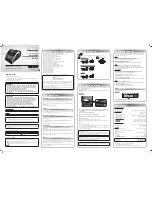
Figure 5.7-1 PWR module
Pin No.
Symbol
Description
01
BO_COM1 Common terminal 1
02
BO_FAIL
Indication of device failure 1 (01-02, NC)
03
BO_ALM
Indication of device abnormality alarm 1 (01-03, NO)
04
BO_COM2 Common terminal 2
05
BO_FAIL
Indication of device failure 2 (04-05, NC)
06
BO_ALM
Indication of device abnormality alarm 2 (04-06, NO)
07
OPTO+
Positive pole of power supply for low-voltage opto-coupler (24V)
08
OPTO-
Negative pole of power supply for low-voltage opto-coupler (24V)
09
Not used
10
PWR+
Positive pole of power supply for device
11
PWR-
Negative pole of power supply for device
12
GND
Grounded connection of device
NOTICE!
The standard rated voltage of PWR module is self-adaptive to 88~300Vdc. For other
non-standard rated voltage, please specify when placing order and check if the rated
voltage of power supply module is the same as the voltage of power source before the
device being put into service.
08020
08020
08020
08020
08020
08020
08020
08020
08020