


3 Operation Theory
PCS-9611 Feeder Relay
3-33
Date: 2014-04-08
The two stages have same protection logics if they are set with definite time characteristics.
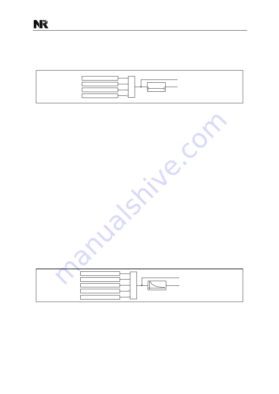
The logic diagram for the stage 1 negative sequence overcurrent protection is shown as below.
The negative sequence overcurrent block is a level detector that detects whether the negative
sequence current magnitude is above the threshold.
I
2
> [50/51Q1.I2_Set]
[50/51Q1.Blk]
[50/51Q1.En]
[50/51Q1.Op]
[50/51Q1.St]
[50/51Q1.En1]
&
t
NOC1
0
Figure 3.7-1 Logical diagram of the stage 1 NOC protection
Where:
[50/51Q1.I2_Set] is the current setting of the stage 1 negative sequence overcurrent
protection;
“t
NOC1
” is the setting [50/51Q1.t_Op], the time setting of the stage 1 negative sequence
overcurrent protection;
[50/51Q1.En] is the logic setting of the stage 1 negative sequence overcurrent protection;
[50/51Q1.En1] is the binary signal for enabling the NOC1 protection;
[50/51Q1.Blk] is the binary signal for blocking the NOC1 protection.
3.7.2 IDMT Negative Sequence Overcurrent Protection
The stage 2 negative sequence overcurrent protection also can be set with inverse definite
minimum time (IDMT) characteristic. It has the same inverse time characteristic with the IDMT
overcurrent protection (see
Section 3.3.2
), and the setting [50/51Q2.Opt_Curve] can be used to
select the expected curve.
The logic diagram of the negative sequence overcurrent protection is shown as below. The
negative sequence current block is a level detector that detects whether the current magnitude is
above the threshold.
I
2
> [50/51Q2.I2_Set]
[50/51Q2.Blk]
[50/51Q2.En]
[50/51Q2.Op]
[50/51Q2.St]
[50/51Q2.En1]
&
IDMT
[50/51Q2.Opt_Curve] = 0
Figure 3.7-2 Logic diagram of the IDMT negative sequence overcurrent protection
Where:
[50/51Q2.I2_Set] is the current setting of the stage 2 negative sequence overcurrent
protection;
[50/51Q2.En] is the logic setting of the stage 2 negative sequence overcurrent pro tection;
Summary of Contents for PCS-9611
Page 1: ...PCS 9611 Feeder Relay Instruction Manual NR Electric Co Ltd...
Page 2: ......
Page 10: ...1 Introduction PCS 9611 Feeder Relay 1 b Date 2014 04 08...
Page 30: ...2 Technical Data PCS 9611 Feeder Relay 2 14 Date 2014 04 08...
Page 36: ...3 Operation Theory PCS 9611 Feeder Relay 3 f Date 2014 04 08...
Page 108: ...4 Supervision PCS 9611 Feeder Relay 4 b Date 2014 04 08...
Page 116: ...5 Management Function PCS 9611 Feeder Relay 5 b Date 2014 04 08...
Page 120: ...5 Management Function PCS 9611 Feeder Relay 5 4 Date 2014 04 08...
Page 218: ...9 Configurable Function PCS 9611 Feeder Relay 9 b Date 2014 04 08...
Page 232: ...9 Configurable Function PCS 9611 Feeder Relay 9 14 Date 2014 04 08...
Page 262: ...11 Installation PCS 9611 Feeder Relay 11 b Date 2014 04 08...
Page 272: ...12 Commissioning PCS 9611 Feeder Relay 12 b Date 2014 04 08...
Page 292: ...13 Maintenance PCS 9611 Feeder Relay 13 b Date 2014 04 08...
Page 296: ...14 Decommissioning and Disposal PCS 9611 Feeder Relay 14 b Date 2014 04 08...
Page 298: ...14 Decommissioning and Disposal PCS 9611 Feeder Relay 14 2 Date 2014 04 08...
Page 300: ...15 Manual Version History PCS 9611 Feeder Relay 15 2 Date 2014 04 08...


