


3 Operation Theory
PCS-9611 Feeder Relay
3-22
Date: 2014-04-08
fault protection, the polarizing signal is required to be a representative of the earth fault condition.
As residual voltage is generated during earth fault conditions, this quantity is commonly used to
polarize DEF elements.
This relay internally derives this voltage from the 3-phase voltage input that must be supplied from
three single-phase voltage transformers. These types of VT design allow the passage of residual
flux and consequently permit the relay to derive the required residual voltage. In addition, the
primary star point of the VT must be earthed. It is possible that small levels of residual voltage will
be present under normal system conditions due to system imbalances, VT inaccuracies, relay
tolerances etc.
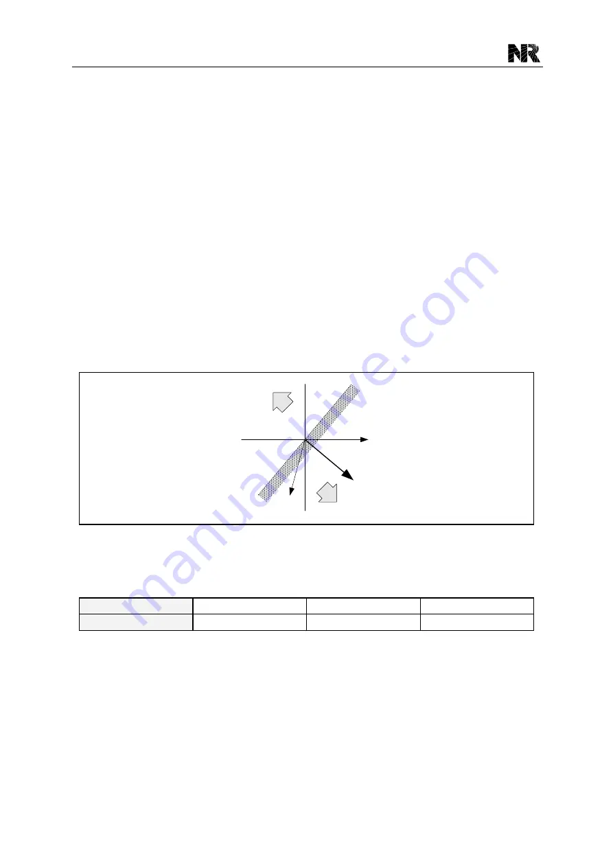
The zero sequence relay characteristic angle (ZS-RCA) is configurable through the setting
[50/51G.RCA]. A directional check is performed based on the following criteria:
Directional forward
-90° < (angle(U
0
) - angle(I
01
) - ZS-RCA) < 90°
Directional reverse
-90° > (angle(U
0
) - angle(I
01
) - ZS-RCA) > 90°
Forward
Reverse
O
U
0
I
01
ZS-RCA
Figure 3.5-3 Operation characteristic of the ROC directional element
The setting [50/51Gx.Opt_Dir] (x: 1~4) is used to select the directional mode for the stage x (x:
1~4) zero sequence overcurrent protection respectively.
Setting Value
0
1
2
Directional Mode
Non-directional
Forward directional
Reverse directional
When the element is selected as directional, a VTS block option is available. When the relevant
setting is set as
“1”, operation of the voltage transformer supervision (VTS) will block the stage if
the relevant directional element is in service. When the relevant setting is set as
“0”, the stage will
revert to non-directional upon operation of the VTS.
The detailed logic diagram of the zero sequence directional element of the stage 1 zero sequence
overcurrent protection is shown as below.
Summary of Contents for PCS-9611
Page 1: ...PCS 9611 Feeder Relay Instruction Manual NR Electric Co Ltd...
Page 2: ......
Page 10: ...1 Introduction PCS 9611 Feeder Relay 1 b Date 2014 04 08...
Page 30: ...2 Technical Data PCS 9611 Feeder Relay 2 14 Date 2014 04 08...
Page 36: ...3 Operation Theory PCS 9611 Feeder Relay 3 f Date 2014 04 08...
Page 108: ...4 Supervision PCS 9611 Feeder Relay 4 b Date 2014 04 08...
Page 116: ...5 Management Function PCS 9611 Feeder Relay 5 b Date 2014 04 08...
Page 120: ...5 Management Function PCS 9611 Feeder Relay 5 4 Date 2014 04 08...
Page 218: ...9 Configurable Function PCS 9611 Feeder Relay 9 b Date 2014 04 08...
Page 232: ...9 Configurable Function PCS 9611 Feeder Relay 9 14 Date 2014 04 08...
Page 262: ...11 Installation PCS 9611 Feeder Relay 11 b Date 2014 04 08...
Page 272: ...12 Commissioning PCS 9611 Feeder Relay 12 b Date 2014 04 08...
Page 292: ...13 Maintenance PCS 9611 Feeder Relay 13 b Date 2014 04 08...
Page 296: ...14 Decommissioning and Disposal PCS 9611 Feeder Relay 14 b Date 2014 04 08...
Page 298: ...14 Decommissioning and Disposal PCS 9611 Feeder Relay 14 2 Date 2014 04 08...
Page 300: ...15 Manual Version History PCS 9611 Feeder Relay 15 2 Date 2014 04 08...


