OEM638 Technical Specifications
Appendix E
OEM6 Family Installation and Operation User Manual Rev 12
183
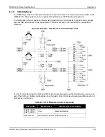
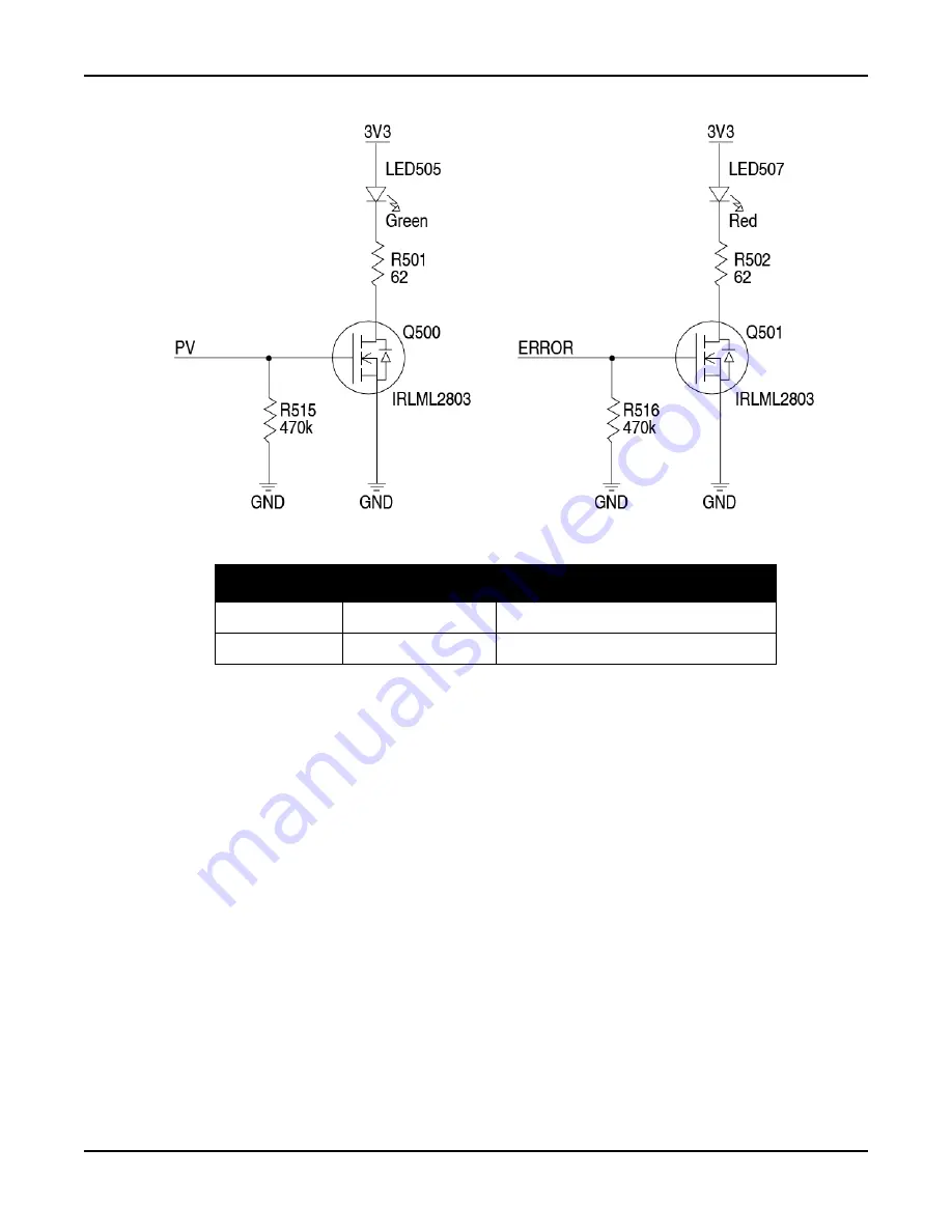
Figure 92: Example - LED Drive Buffer for PV and ERROR Signals
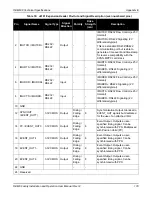
Table 41: Bill of Materials (critical components)
E.1.5
Communication Ports
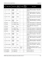
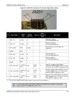
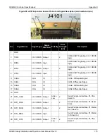
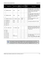
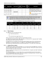
COM1, COM2 and IMUCOM (COM6) present software-selectable RS232 or RS422 signal levels. RTS/CTS
flow control is available on each port. COM1 and IMUCOM are protected to ±15 kV (HBM) discharges. COM2
is protected to ±26 kV (HBM) discharges. Additional ESD protection is recommended near the enclosure
connectors for any signal leaving an enclosure.
COM3, COM4 and COM5 are 3.3 V CMOS-level signals only. RTS/CTS flow control is available for each
interface but COM2 also has DTR/DCD flow control (for reverse-compatibility with the OEMV-3G receiver).
These signals are 3.3 V CMOS UARTs that require an external transceiver to connect to an RS232 or RS422
device. These pins have some ESD protection but (again) additional ESD protection near the connectors for
any signals leaving an enclosure is recommended.
A combination of a series ferrite bead and small value shunt capacitor is recommended on any RS232/
RS422 lines that leave the enclosure (similar to the arrangement used on the I/O ports and CAN interfaces
below). (The TVS recommended for 3.3 V CMOS-level I/O is unsuitable for RS232-level I/O. An additional
low capacitance TVS device with a clamping voltage between 18 V and 25 V should be selected for RS232
lines requiring additional protection.)
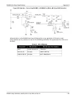
Designator
Manufacturer
Manufacturer Part Number
U202
Texas Instruments
SN74LVC1G86DCK
D214, D215
Semtech
uClamp3304A.TCT


