


138
OEM6 Family Installation and Operation User Manual Rev 7
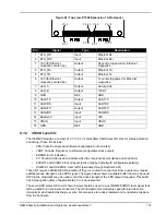
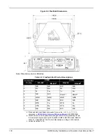
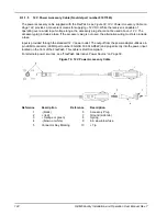
Figure 69: FlexPak6 Dimensions
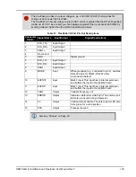
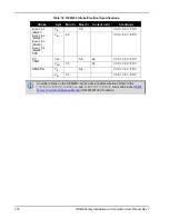
Table 30: FlexPak6 Port Pin-Out Descriptions
Connector
Pin No.
COM1
COM2
RS-232
RS-422
a
a.
Mode selected via software commands. Refer to the
SERIALPROTOCOL
command in
OEM6 Family Firmware Reference Manual
(OM-20000129).
RS-232
RS-422
b
b. COM2 can be can be dynamically changed to RS-422 by grounding I/O pin
9. Connect pin 5 (ground) to pin 9 to switch COM2 to RS-422 mode. Refer to
Table 31, FlexPak6 I/O Port Pin-Out Descriptions
for details.
1
N/C
N/C
N/C
N/C
2
Rx
Rx+
Rx
Rx+
3
Tx
Tx+
Tx
Tx+
4
N/C
N/C
POUT
c
c. Current is limited to 1 A.
POUT
c
5
GND
GND
GND
GND
6
N/C
N/C
N/C
N/C
7
RTS
Tx-
RTS
Tx-
8
CTS
Rx-
CTS
Rx-
9
N/C
N/C
N/C
N/C
Note: Dimensions are in millimetres.