~ 29 ~
NOVATEK-ELECTRO
UBZ-304
When
“Relay F mode” =
“Alarm”
, the relay is used as alarm relay (LEDs
and
TR
do not on). The relay
contacts are closed when there is any fault specified in Table 5.13.
When
“Relay F mode” = “Timer”
, the relay is used as time relay (LED
TR
is on): it turns on after the time set by
the parameter
“Relay F time”,
after the load relay enabling.
When
“Relay F mode” = “St
-
>D”
, the relay is used to switch the motor windings from star to delta (LED "
"
is on). In this mode the load relay is activated the same way as in the mode
“Relay F mode”=”Alarm”
, but after the
time set by parameter
“Relay F time”
it is disabled. After the time set by the parameter
“Delay RP RF",
after the load
relay is off, the functional relay is activated.
N o te
–
When the functional relay is enabled, the contacts
13-14
are open, and contacts
14-15
closed.
5.4 OPERATION OF UBZ-304 TOGETHER WITH COMPUTER
5.4.1 Communication protocol and interface
The communication between UBZ and computer can be via RS-232 or RS-485 interface (parameter
"Communication").
For communication MODBUS Protocol is used in
RTU
mode or MODBUS in
ASCII
mode (parameter "ASCII-RTU ").
In ASCII mode 8-bit data is the combination of two ASCII characters (Table. 5.2). For example, 1
–
data byte:
64 Hex, in ASCII consists of two characters '6' (36 Hex) and '4' (34 Hex).
Table 5.2
Character
'0'
'1'
'2'
'3'
'4'
'5'
'6'
'7'
ASCII code
30 Hex
31 Hex
32 Hex
33 Hex
34 Hex
35 Hex
36 Hex
37 Hex
Character
'8'
'9'
'A'
'B'
'C'
'D'
'E'
'F'
ASCII code
38 Hex
39 Hex
41 Hex
42 Hex
43 Hex
44 Hex
45 Hex
46 Hex
In
RTU
mode 8-bit data is the combination of 4-bit hexadecimal digits. For example, 64 Hex.
During data exchange via RS-485 or RS-232 the blue LED
EXCHANGE
is on.
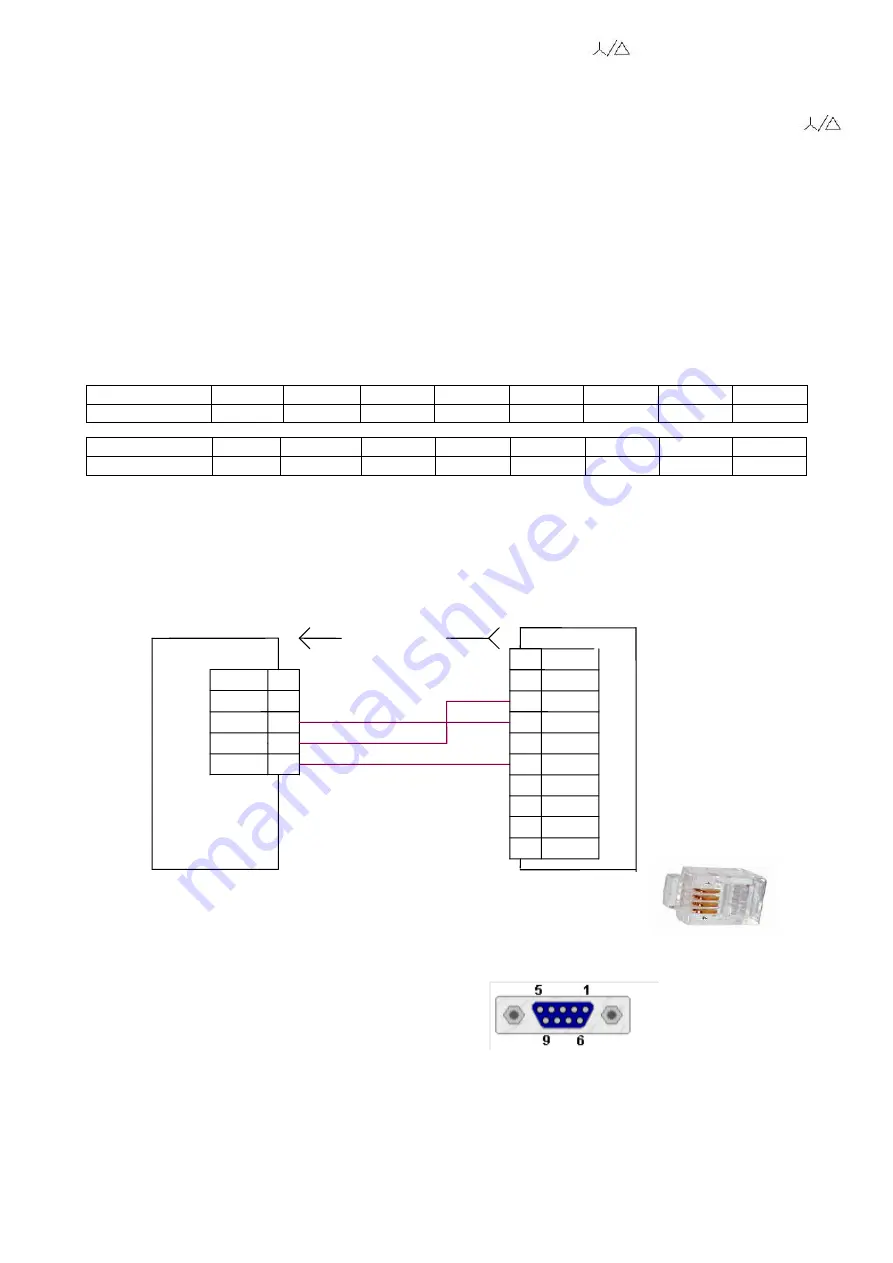
Diagram of UBZ connection to computer is shown in Fig.5.12.
Each UBZ has the individual communication address. The computer controls each UBZ recognizing them by
their addresses.
3
RxD
GND
1
UBZ-304
X2
Cont
8
X1
X2
X1
Computer
2
Plug for connecting of the handset PLUG-4P4C-P-C2
"
RS-232
"
Cont
4
Socket DB-9
com-port
9
1
5
Designation
Designati
on
6
TxD
2
3
TxD
7
RxD
4
SG
Figure 5.12
–
Diagram of UBZ connection to computer
5.4.2 Communication parameters:
–
the unit address: 1-247 (parameter
“Address UBZ”
);
–
data transfer rate: 9600 baud, 19200 baud (parameter
“Data speed”
);
–
reaction to loss of connection: the continuation of operation with no warning, the warning and continued
operation, the warning and stopping the motor with ARS enabling after restoration of communication, warning and
motor stop with ARS disabling (parameter
“Loss connect”
);
–
detection of exceeded time for reply: 1s
–
120s (parameter
“
Overex
ceeding”
).
The format of the transmitted word is the following:
–
8 data bits in RTU mode and 7 data bits in ASCII mode;
–
parity check (parameter "Even parity"): disabled ("Off"), enabled ("On"); (factory setting is "Off");
–
number of stop bits (parameter "Stop bit"): 1 or 2 (factory setting is 2).


