


REMOTE INTERLOCK FUNCTIONS
PAGE
|
59
Lasing is enabled when a Remote Interlock signal is present (INT LED illuminated green), if the RDY LED
is illuminated and a Shutter Open Request signal is applied. Lasing is disabled when the Remote Interlock
signal is removed (INT LED red, RDY LED off). DC power is applied to the RF driver only when the INT
LED is green and the RDY LED is yellow. Remote interlock functionality is provided by the Remote
Interlock signal via Pin 3 on the User I/O connector.
To use ’s remote interlock feature to initiate lasing, apply a voltage in the range of ±5–24 VDC to Pin 3,
Remote Interlock. Applying a Remote Interlock signal causes the INT LED to turn green, the RDY
indicator to turn yellow, and sends DC power to the laser’s RF boards. After a five-second delay, a tickle
signal is applied to the tube. When a Shutter Open Request signal is present, PWM Command signals are
enabled to begin lasing. Removing voltage stops DC power from reaching the RF driver, causing the INT
LED to turn red and the RDY LED to turn Off. Lasing remains disabled until a voltage is reapplied to Pin
3.
Your control system can monitor the laser’s remote interlock status on the User I/O connector by
connecting your system’s input to Pin 15, Interlock Open, and Pin 13, Output Common (see Figure 4-25).
This output is closed when remote interlock circuitry is open (INT LED illuminated red). The output is
open (INT LED green) when interlock circuitry is closed.
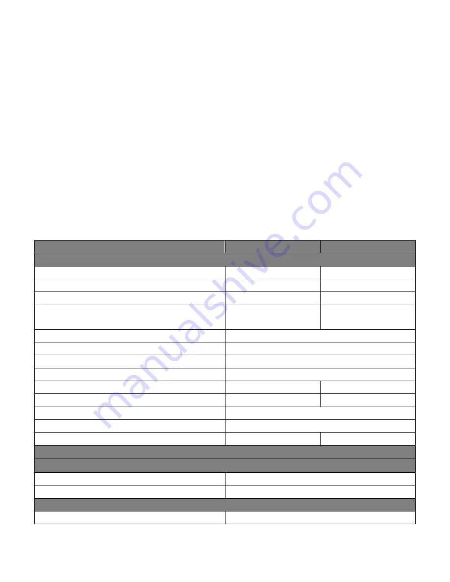
Table 3-10 p100 general specifications.
Perimeter
p100 (10.2
μ
m)
p100 (10.6
μ
m)
Output Specifications
Wavelength typical (
μ
m)
10.25
±
±0.1
10.6
±
±0.1
Average Power Output (minimum)
2
90 W
100 W
Peak Power, typ
1
375 W
400 W
Peak Pulse Energy, (maximum)
180 mJ (tested at 625 Hz, 37.5%
Duty
Cycle)
190 mJ (tested at 625 Hz, 37.5%
Duty Cycle)
Power Stability, from cold start (typ)
3
±
7%
Power Stability, after 3 min (typ)
3
±
5%
Mode Quality
3
M
2
≥
1.2
Beam Waist Diameter (at 1/e2)
3
7.5 mm
±
1.1 mm
Beam Waist Diameter at faceplate (at 1/e2)
3
7.5 mm
±
1.1 mm
8.0 mm
±
1.0 mm
Beam Divergence, full angle (at 1/e2)
3
1.8 mrad
±
0.4 mrad
2.0 mrad
±
0.4 mrad
Ellipticity3 & Ellipticity far field
3
≤
1.2
Polarization
Linear, vertical
Rise and Fall Time
1
< 40
μ
s (Rise) < 80
μ
s (Fall)
< 40
μ
s (Rise) < 100
μ
s (Fall)
Input Specifications
Power Supply
Input Voltage / Current (maximum)
48 VDC / 40 A
Peak Current Amps
75 A (for < 700
μ
s)
Command Input Signal
Voltage
+3.5 to +6.7 VDC (5V nominal)
Summary of Contents for SYNRAD Pulstar p100
Page 1: ...ENGINEERED BY SYNRAD p100 150 Lasers User Manual...
Page 17: ...NOMENCLATURE CONTINUED PAGE 12 Nomenclature Continued Figure 1 2 Anatomy of a model number...
Page 23: ...ADDITIONAL LASER SAFETY INFORMATION PAGE 18 p100 label locations...
Page 24: ...ADDITIONAL LASER SAFETY INFORMATION PAGE 19 p150 label locations...
Page 30: ...ELECTROMAGNETIC INTERFERENCE STANDARDS PAGE 25 Figure 2 1 p100 Declaration Document...
Page 31: ...ELECTROMAGNETIC INTERFERENCE STANDARDS PAGE 26 Figure 2 2 p150 Declaration Document...
Page 39: ...FOCUSING OPTICS PAGE 34 Table 3 1a Dew point temperatures in Fahrenheit Dew Point Table F...
Page 46: ...OPERATION MODES PAGE 41 Figure 3 6 p150 pulse profile 37 5 duty cycle at 10 kHz...
Page 49: ...USER I O CONNECTION SUMMARY PAGE 44 Figure 3 9 User I O connector pinouts...
Page 68: ...REMOTE INTERLOCK FUNCTIONS PAGE 63 Figure 3 21 p100 150 outline mounting drawings pg 1 of 2...
Page 70: ...REMOTE INTERLOCK FUNCTIONS PAGE 65 Figure 3 23 p100 150 packaging instructions...
Page 71: ...REMOTE INTERLOCK FUNCTIONS PAGE 66 Figure 3 24 p150 outline and mounting...
Page 79: ...STATUS LEDS PAGE 74 Status LEDs Table 4 2 p100 p150 Input output LED Status Signals...


