LED PAR 19X10 Product Datasheet
LED PAR 19X10 Product Datasheet
05
06
Cautions:
6.
INSTALLATIONS
7.
CONTROL CONNECTION
For added protection mount the fixtures in areas
outside walking paths, seating areas, or in areas
where the fixture might be reached by
unauthorized personnel.
Before mounting the fixture to any surface, make sure
that the installation area can hold a minimum point
load of 10 times the
device’s
weight.
Fixture installation must always be secured with a
secondary safety attachment, such as an appropriate
safety cable.
Never stand directly below the device when mounting,
removing, or servicing the fixture.
from a ceiling, or set on a flat level surface (see
illustration below). Be sure this fixture is kept at least
0.5m (1.5 f t) away from any flammable materials
(decoration etc.).
Always use and install the supplied safety cable as a
safety measure to prevent accidental damage and/or
injury in the event the clamp fails.
Mounting points:
Overhead mounting requires extensive experience,
including amongst others calculating working load
limits, a ne knowledge of the installation material
being used, and periodic safety inspection of all
installation material and the fixture. If you lack these
qualifications, do not attempt the installation yourself.
Improper installation can result in bodily injury.
Be sure to complete all rigging and installation
procedures before connecting the main power cord to
the appropriate wall outlet.
Clamp Mounting:
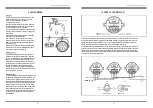
The LED PAR 19X10 provides a unique mounting bracket
assembly that integrates the bottom of the base, and
the safety cable rigging point in one unit (see the
illustration below). When mounting this fixture to truss
be sure to secure an appropriately rated clamp to the
included omega bracket using a M10 screw fitted
through the center hole of the handle. As an added
safety measure, be sure to attached at least one
properly rated safety cable to the fixture using one of
the safety cable rigging points integrated in the
base assembly.
Connect the provided XLR cable to the female 3-pin XLR output of your controller and the other side to the
male 3-pin XLR input of the moving head. You can chain multiple Moving head together through serial
linking. The cable needed should be two core, screened cable with XLR input and output connectors.
Please refer to the diagram below. DMX-512 connection with DMX terminator.
For installations where the DMX cable has to run a long distance or is in an electrically noisy environment,
such as in a discotheque, it is recommended to use a DMX terminator. This helps in preventing corruption of
the digital control signal by electrical noise. The DMX terminator is simply an XLR plug with a3 resistor
connected between pins 2 and 3, which is then plugged into the output XLR socket of the last fixture in the
chain. Please see illustrations below.
DMX IN
DMX OUT
POWER OUT
POWER IN
DMX512 OUT
DMX512 IN
Signal (-)
1 2
Signal (+)
Ground
3
120
Ω
2
1
Signal (-)
3
Signal (+)
DMX IN
POWER IN
Safety Clamp
Safety Cable


