background image


            SiteTel Sweden AB Haukadalsgatan 8A, SE-164 40 Kista, Sweden 

www.northbattery.com  


S

ITE

S

TAR 

C

ABINET


M

AINTENANCE 

I

NSTRUCTIONS


Product No: D000100/3 

Revision: R2A 

Summary of Contents for SiteStar D000100/1

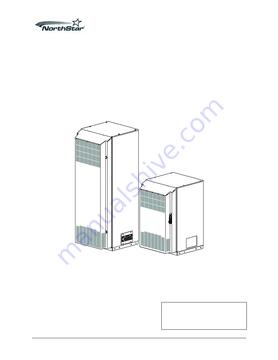
Page 1: ...SiteTel Sweden AB Haukadalsgatan 8A SE 164 40 Kista Sweden www northbattery com SITESTAR CABINET MAINTENANCE INSTRUCTIONS Product No D000100 3 Revision R2A ...

Page 2: ... damage of any kind resulting from the use of this document Contents 1 INTRODUCTION 4 1 1 Target Group 4 1 2 Documents 4 1 3 Illustrations 4 1 4 Prerequisites 4 1 5 Abbreviations 4 2 HEALTH AND SAFETY INFORMATION 5 2 1 Batteries 5 2 2 Electrical Equipment 7 2 3 Refrigerant 8 2 4 RoHS WEEE 9 2 5 In Case of Fire 9 2 6 Damages 10 3 TOOLS AND EQUIPMENT 10 4 GENERAL TORQUES DURING MAINTENANCE 11 5 OPEN...

Page 3: ...htening the Battery Cable Connectors 18 7 TROUBLESHOOTING 19 7 1 Alarm 19 7 2 Mechanics 20 7 3 DC Output 20 7 4 Cooling Heating 21 7 5 Leakage 21 8 RECONFIGURING THE EXTERNAL ALARM 22 9 REPLACING BATTERIES 24 9 1 Remove Batteries 24 9 2 Installing Batteries 28 10 SPARE PARTS 36 ...

Page 4: ...inet and its handling D000100 1 SiteStar Cabinet Description D000100 2 SiteStar Cabinet Installation D000100 4 SiteStar Spare Parts 1 3 ILLUSTRATIONS Illustrations in this document can show alternative designs 1 4 PREREQUISITES All performance statement in this document relies on the following Only approved hardware are used Proper hardware handling Maintenance instructions as well as documentatio...

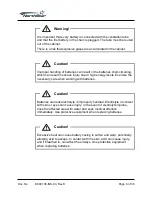
Page 5: ...ste Electrical and Electronic Equipment 2 HEALTH AND SAFETY INFORMATION 2 1 BATTERIES Warning High energy levels are present in this unit Improper handling of the unit can lead to short circuiting that can result in serious injury Exercise care when working with this unit Warning To avoid battery thermal runaway the batteries must be connected to an external PSU with thermal compensated charging F...

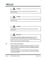
Page 6: ... due to high energy levels Exercise the necessary care when working with batteries Caution Batteries can leak electrolyte if improperly handled Electrolyte in contact with skin or eyes can cause injury In the event of electrolyte injuries rinse the affected area with water and seek medical attention immediately Use protective equipment when replacing batteries Caution Excessive heat can cause batt...

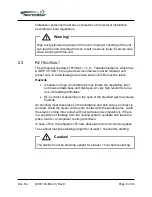
Page 7: ...rtance that the Battery cables are provided with adequate protection at the site to ensure compliance to national wiring regulations Risk of personal injury and property damage 2 2 ELECTRICAL EQUIPMENT Installation personnel should exercise care when working on or around electrical equipment In addition to this safety information the specific safety instructions for all products involved in the in...

Page 8: ...ntrations may irritate the respiratory tract and cause drowsiness and dizziness At very high levels there is a risk of breathing difficulties Skin contact or splashing in the eyes of the liquefied gas may cause frostbite All handling must take place so that inhalation and skin and eye contact is avoided Avoid the steam coming into contact with the welding arcs Avoid the steam coming into contact w...

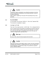
Page 9: ...e care of any injured persons Call for help Try to extinguish the fire Only use approved fire extinguisher for extinguishing electrical equipment After a fire the cabinet insulation might has been damaged In this case the cabinet strength will be considerably reduced and can cause the cabinet to collapse when opening the door Warning In case of fire toxic and corrosive gases will be formed Caution...

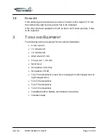
Page 10: ...ely it has to be replaced 3 TOOLS AND EQUIPMENT The following tools are required for the cabinet installation 8 mm wrench 13 mm wrench 18 mm wrench Allen wrench 5 mm Torque set 1 80 Nm Spirit level Screwdriver 0 4x2 5xL Screwdriver PZ 2 Torx T20 screwdriver only when changing from left hanged door to right hanged door Torx T25 screwdriver Torx T30 screwdriver Torx T45 screwdriver Insulated tools f...

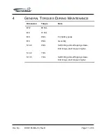
Page 11: ...TENANCE Dimension Torque Note M12 80 Nm M8 15 Nm M8 8 Nm For battery poles M6 9 Nm Generally St 4 8 4 Nm Self drilling and self tapping screws End torque start torque is higher St 4 2 1 Nm St 3 5 1 Nm Self drilling and self tapping screws End torque start torque is higher ...

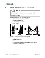
Page 12: ...sk of personal injury Do as follows to unlock and open the cabinet door 1 Raise the cabinet to a standing position 2 Unlock the swing handle 3 Lift and turn the swing handle 4 Open the door Figure 1 Unlocking and Opening Swing Handle Do as follows to close and lock the cabinet door 1 Release the door latch 2 Close the door 3 Turn and push the swing handle to locked position The swing handle will l...

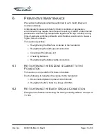
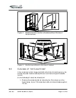
Page 13: ...te a higher risk of corrosion This section describes Re tightening the EQ Zone 4 cabinet to the foundation Re tightening the earth ground connection Cleaning of the climate unit Checking batteries Re tightening the battery cable connectors 6 1 RE TIGHTENING THE EQ ZONE 4 CABINET TO THE FOUNDATION This section is only valid for EQ Zone 4 Cabinets Do the following to re tighten the cabinet to the fo...

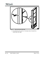
Page 14: ... 6 3 CLEANING OF THE CLIMATE UNIT If the condenser is fully clogged with dirt at the first 24 months service the service intervals must be narrowed down to remain a long term reliable system Do the following to clean the climate unit 1 Remove the swing handle by removing the Torx screw as in the figure below Use a T30 screwdriver with a minimum blade length of 75 mm ...

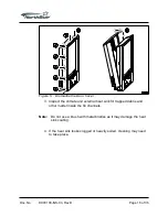
Page 15: ...Doc No D000100 INS 03 Rev D Page 15 of 36 Figure 4 Remove the Swing Handle 2 Dismantle the door cover as in the figure below Start with the screws A at the sides ...

Page 16: ...er 3 Inspect the climate unit external heat sink for trapped debris and other matter inside the fin channels Note Do not use a brush with metal bristles as it may damage the heat sink coating 4 If the heat sink looks clogged or heavily soiled cleaning may need to take place ...

Page 17: ... D Page 17 of 36 Figure 6 Heat Sink 5 Brush off any loose debris from the louvers at the door cover Note Strong detergents must be avoided as they can be aggressive to aluminum and potentially cause unwanted corrosion in wiring ...

Page 18: ...attery Telecom Application Manual for procedure This document is available on request 6 5 RE TIGHTENING THE BATTERY CABLE CONNECTORS The battery cable connectors needs to be re tightened after every battery replacement and when installing new batteries Refer to the battery supplier for recommended torque ...

Page 19: ...f the fan works 3 Check if the CCU works correctly Internal temperature outside regulation window too low Install optional heater If heater is installed check heater and relay if equipped Compressor fails Replace door Heater fails if equipped Replace heater Fan fails Replace fan Controller internal error Replace controller External temperature outside system specification See section 7 4 Door swit...

Page 20: ...he door has been damaged If necessary replace the door Check if the cabinet has been damaged If necessary replace the cabinet 7 3 DC OUTPUT Problem What to do No voltage Check battery connection If equipped check DCCU fuse For further guidance check PSU and battery manuals Voltage too high or too low Check if the battery configuration is right Check battery connection Check batteries ...

Page 21: ...emperature sensor If the temperature sensor is ok replace control board The fan does not work Check connections If the fan still does not work replace it to a new one 7 5 LEAKAGE Problem What to do Water in the cabinet Check possible water from condensation Check If the drain tube is clogged Check possible water leakage from outside the cabinet If necessary replace damaged sealing s Check if the d...

Page 22: ...summary alarm NO or NC on alarm output K1 Do as follows to reconfigure from individual to summary alarm 1 Disconnect power 2 Remove the CCU Front Plate a Loosen the five screws holding the CCU Front Plate No 1 in the figure below b Lean the CCU Front Plate forward No 2 in the figure below Figure 7 Removing CCU Front Plate 3 Locate configuration connector P16 4 Remove the configuration jumper as sh...

Page 23: ...Doc No D000100 INS 03 Rev D Page 23 of 36 Figure 8 Reconfiguring for Summary Alarm 5 Reinstall the CCU Front Panel 6 Reconnect power ...

Page 24: ...OVE BATTERIES Make sure that all power is disconnected before any works starts If the cabinet is an EQ Zone 4 cabinet the EQ Zone 4 reinforcement in front of the batteries has to be removed before the batteries can be removed Do as follows to remove the reinforcements 1 Remove the cross braces as in Figure 9 Figure 9 Remove Cross Braces ...

Page 25: ...Doc No D000100 INS 03 Rev D Page 25 of 36 2 Remove the front bars as in Figure 10 Figure 10 Remove Front Bars ...

Page 26: ...s in Figure 11 Figure 11 Remove Corner Pieces Disconnect the Batteries Make sure that all power at the external power supply are switched off before any work starts Do as follows to disconnect the batteries 1 Remove the pole protections Figure 12 Removing Pole Protections ...

Page 27: ...gs Figure 13 Removing Battery Cable 3 Insulate the cable lugs Figure 14 Insulating Cable Lug 4 Remove the fuses in the DCCU if equipped 5 Remove the three inter block connectors connecting the batteries to each other Figure 15 Removing Inter block Connectors 6 Remove the gas ventilation tubes ...

Page 28: ... sensor holder and install battery block no 2 Install battery block no 4 most to the right on the shelf Install battery block no 3 The distances between the battery blocks are normally given by the inter connections and the spacers To ensure necessary air circulation around the battery blocks it is important to keep a minimum distance of 7 mm between the battery blocks The distance between the wal...

Page 29: ...er It is recommended that when installing new batteries also install new ventilation tubes Do the following to connect the gas ventilation tubes 1 Cut the venting tube in four pieces for each battery string three pieces with length 110 mm the fourth tube is the remaining length Use the short pieces for connecting the batteries in the battery string as in Figure 17 2 Use the long tube and connect t...

Page 30: ...Doc No D000100 INS 03 Rev D Page 30 of 36 Figure 18 Connecting Gas Ventilation Tube Figure 19 Routing Gas Ventilation Tube For more information see the installation instruction for the battery kit ...

Page 31: ...necting batteries can result in short circuiting which can result in serious injury due to high energy levels Exercise the necessary care when working with batteries Secure that not connected cable lugs are insulated Connect the battery blocks into a battery string according to the following 1 Attach the three inter block connectors between battery block no 1 and no 2 between battery block no 2 an...

Page 32: ...Nm Figure 21 Connecting Negative Cable 3 Connect the positive cable to battery block no 4 using M8 bolt and washer Tighten to a torque of 8 Nm The battery string positive cable is not to be connected until all connections to the CF have been made Figure 22 Connecting Positive Cable 4 Fit the pole protections Figure 23 Fitting Pole Protections ...

Page 33: ... reinstall the corner pieces to the EQ Zone 4 structure as in Figure 24 Tighten the four M6 screws at each corner to a torque of 9 Nm Figure 24 Reinstalling Corner Pieces Fit the front bars to the EQ Zone 4 structure as in Figure 25 Note Use the inner front bar position for the 100 Ah batteries Use the outer front bar position for the 170 180 Ah batteries Tighten the six M6 screws at each front ba...

Page 34: ...Doc No D000100 INS 03 Rev D Page 34 of 36 Figure 25 Reinstalling Front Bars Fit the cross braces to the corner pieces as in Figure 26 Tighten the turnbuckles stretchers by hand ...

Page 35: ...Doc No D000100 INS 03 Rev D Page 35 of 36 Figure 26 Reinstalling Cross Braces ...

Page 36: ...Doc No D000100 INS 03 Rev D Page 36 of 36 10 SPARE PARTS See D000100 4 SiteStar Cabinet Spare Parts for spare parts suitable for the SiteStar Cabinet ...

Reviews: